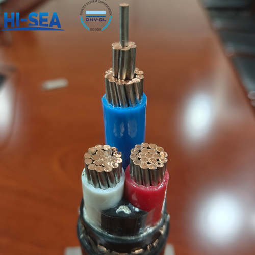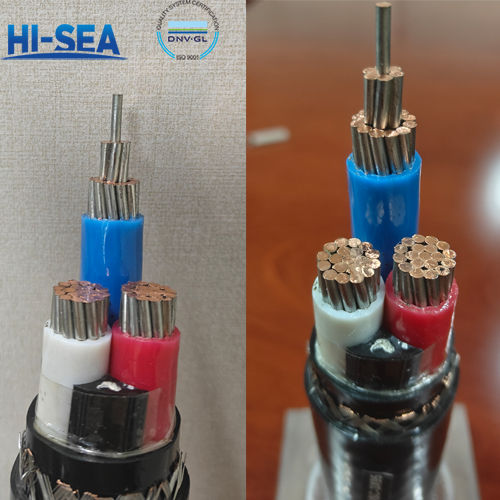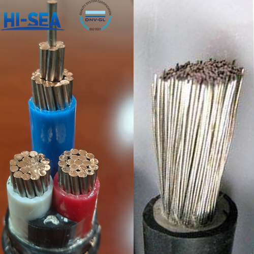

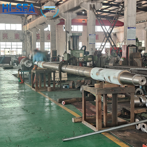
What is the stern shaft?
The stern shaft generally refers to the last section of a ship's shaft system with a propeller. On some ships, due to the shape of the ship or the inclination of the shaft system, the shaft system extends beyond the hull. The last section of the propeller shaft is called the propeller shaft, and the front sections of the shaft that extend outside the hull are collectively referred to as the stern shaft. The fit between the tail shaft and the thruster adopts a conical surface, and the thruster is pressed onto the shaft with the tail shaft nut. The thread direction of the tail shaft nut must be opposite to the forward direction of the thruster to prevent loosening. When the stern tube bearings are lubricated and cooled with outboard water, the parts where the stern shaft comes into contact with the outboard water (between the front and rear copper sleeves) are usually coated with fiberglass for corrosion prevention. During maintenance, attention should be paid to the looseness, peeling, and wear of the copper sleeve.
Overview
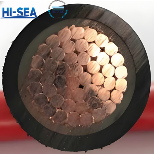
Figure 1-30 shows the structure of the stern shaft, where Figure (b) shows the stern shaft structure of a forged flange (or welded flange); Figure (a) shows the structure of the detachable flange stern shaft, which is wrapped with copper sleeves on the front and rear necks of the stern shaft, and coated with glass cloth soaked in epoxy resin on other non working surfaces for corrosion prevention. This structure is most commonly used in ships in coastal areas. The stern shaft is installed in the stern tube that passes through the hull and is supported on the stern tube bearings. Its front end is connected to the intermediate shaft (or thrust shaft) through a coupling (flange), and the propeller is fixed on the stern shaft by a nut on the cone. The thread direction of the fastening nut should be opposite to the direction of the ship's forward direction to avoid nut loosening and accidents. In addition, the nut should also have a locking device (such as a stopper, anti loosening screw, positioning block, etc.). There should be a minimum of 3-4 points of contact on the mating surface of the tapered hole, detachable coupling, and stern shaft cone of the propeller within a 25mm x 25mm area.
For more marine stern shaft information, kindly please click here.
For more marine shaft system components, kindly please click here.