Distribution Transformer
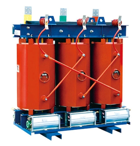
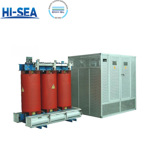
A distribution transformer is a stationary device in a distribution system that transmits alternating current (AC) power by transforming AC voltage and current through the application of the law of electromagnetic induction. It operates at voltage levels of 10-35KV in the distribution network, with a typical capacity not exceeding 6300KVA. Distribution transformers supply power directly to end users.
Overview
Standard: conform to the standards of GB 1094.1-2013, GB 1094.11-2007, GB/T 10228-2008
Application
Distribution transformers are widely used in power transmission and transformation systems, hotels, restaurants, high-rise buildings, commercial centers, stadiums, petrochemical plants, subways, stations, airports, offshore drilling platforms, and other locations.
Product information
Capacity range: 30-2500kVA
Voltage level: 10kV, 20kV, 35kV
Voltage regulation mode: no-excitation voltage regulation or on-load voltage regulation
Tap range: ±5%, ±2×2.5%, ±4×2.5%
Frequency: 50Hz or 60Hz
Number of phases: three-phase
Connection group number: Y, yn0, D, yn11 or other
Short-circuit impedance: standard impedance (see performance parameters)
Use conditions: altitude less than 1000m, ambient temperature not higher than 40℃. When the above-mentioned use conditions are exceeded, the corresponding quota adjustment shall be made according to the standard
Cooling method: self-cooling (AN) or air cooling (AF)
Protection level: IP00, IP20 (indoor), IP23 (outdoor)
Insulation level: F class
Insulation level: 10kV level: LI/AC 75/35 kV
20kV level: LI/AC 125/50 kV
35kV level: LI/AC 170/70 kV
0.4kV level: AC /3 kV
Climate level: C2
Environmental level: E2
Combustion performance level: F1
Characteristic
Small size, lightweight, and easy to install.
Coils use the same winding technology, ensuring good concentricity and strong short-circuit resistance.
Iron core lamination is tightly bonded, resulting in low loss and low noise.
Flame-retardant, explosion-proof, and environmentally friendly.
Utilizes air natural cooling method, providing good heat dissipation performance.
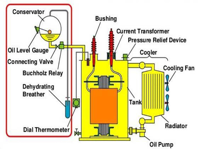
The structure of a basic distribution transformer
Working principle
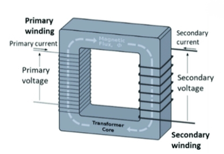
When an alternating current (AC) flows through the primary winding, it generates an alternating magnetic flux. This alternating magnetic flux, guided by the iron core, induces an alternating electromotive force (EMF) in the secondary winding, thereby transmitting electrical energy. The magnitude of the induced secondary EMF is related to the number of turns in the primary and secondary windings, that is, the voltage is proportional to the number of turns.
Product show
