
Composition of Marine Shaft System
The marine shaft system is a fundamental component of the ship's power plant. It serves as a bridge between the output end of the main engine (gearbox) and the propeller. The marine shaft system mainly consists of the main engine, thrust shaft, thrust bearing, intermediate shaft, bulkhead packing/stuffing box, intermediate bearing, stern shaft, stern tube, propeller, stern shaft oil tank, etc.
Overview
The marine shaft system is a fundamental component of the ship's power plant. It serves as a bridge between the output end of the main engine (gearbox) and the propeller.
Every ship has a certain distance from its engine room to the stern, especially for some ships with main engine compartments located in the middle of the hull, their shaft systems are very long, some even up to hundreds of meters. It is unrealistic to make such a long transmission shaft system into a single unit. Therefore, for the convenience of manufacturing, processing, lifting, and disassembly and maintenance, shipyards often divide the shaft system into many sections and connect them with couplings (also known as coupling flanges or Kopling) according to the axis requirements. And each shaft can be divided into thrust shaft, intermediate shaft, and stern shaft (propeller shaft) according to its purpose.
For more marine shaft system information, kindly please click here.
For more marine shaft system components, kindly please click here.
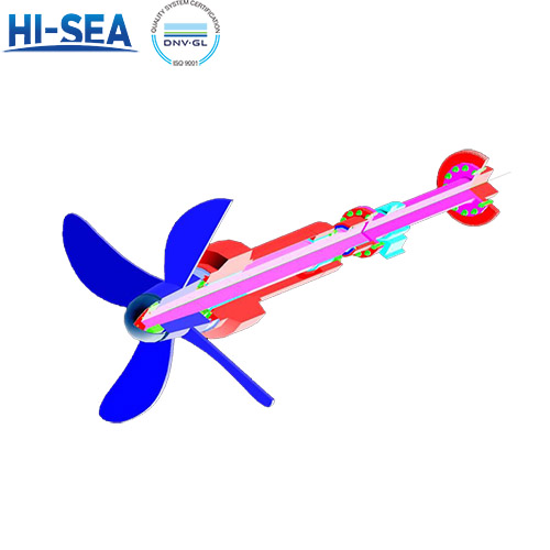
Figure 1-14 shows the shaft system of a direct transmission. It consists of the following.

Main engine: (No. 1) It is the main engine of ship propulsion in the form of direct transmission. This type of main engine can operate in both forward and reverse directions to meet the power requirements of the propeller. For diesel engines that use medium to high speeds or non-reversible engines, additional equipment such as a reduction gearbox and clutch should be installed behind the main engine.
Thrust shaft: (No. 2) Its front end is connected to the output coupling of the main engine or gearbox by a coupling (flange, Kobylin), and its rear end coupling is connected to the coupling of the intermediate shaft. The combination of thrust shaft and thrust bearing forms a complete component.
Thrust bearing: (No. 3) It is the thrust transmitted through the thrust shaft when the propeller does work, and then transmits the thrust to the hull through itself, causing the hull to move forward or backwards.
The intermediate shaft: (No. 4) is used to connect the thrust shaft and stern shaft.
Intermediate bearing: (No. 6) is mainly used to bear the radial load and gravity of the intermediate shaft.
Filler Li for compartment: (No. 5) is used to maintain the water tightness of the shaft system passing through the watertight compartment,
Stern shaft: (or propeller shaft): (No. 7) used to connect the intermediate shaft and propeller, and to drive the rotation of the propeller.
A stern shaft tube: (No. 9) is used to support the propeller and energy shaft and to rotate them within it. Oil seals or water sealing devices are usually installed here to maintain sealing.
Stern tube support: (No. 8) is mainly used to support the stern tube. When shipyards build new ships, to ensure the quality of the axis and the correct installation of the stern tube, it is generally necessary to perform on-site boring of the bore diameter of the stern tube support.
Propeller: (No. 1) (Figure 1-15) The propeller is usually installed at the stern of the ship and is not submerged. It is connected to the main engine with a steel shaft and performs rotational motion. When the propeller rotates, the blades push the water backwards, and due to the reaction force of the water, the ship is pushed forward. Generally, ships are equipped with one propeller, but there are also two; On warships, there are three to four propellers installed, which have high efficiency and simple processing technology, making them the most widely used ship propulsion system.
A propeller is used to propel a ship forward or backwards. Its shape resembles the blades of a fan, so it is also known as a "car leaf".

In short, the number and length of shafts, as well as the configuration of accessories, are often related to the ship type, size, engine position, and type of power device.