
Understanding Marine Oil Separators
A marine oil separator is a critical piece of shipboard equipment designed to separate water, impurities, or other non-oil substances from oil-water-impurity mixtures. It is commonly used for the purification of fuel oil, lubricating oil, and other related systems.
Overview
I. Structural Composition of Marine Oil Separators
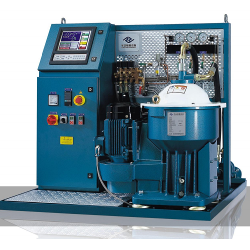
Most marine oil separators adopt a centrifugal structure, with a typical configuration including the following components:
1. Centrifugal Separation System (Core Component)
Rotating Drum
As the core separation component of the oil separator, it is made of high-strength materials such as stainless steel. It rotates at high speed along with the main shaft to generate centrifugal force. Its internal structure is designed based on separation requirements, mainly consisting of:
Separation Discs: A set of conical discs (ranging from dozens to hundreds in number) with tiny gaps between them. When the oil flows through these gaps, under the action of centrifugal force, water and impurities with higher density are thrown to the outer side of the discs and discharged along the inner wall of the rotating drum, while the purified oil accumulates towards the center.
Oil Distributor: Located at the top of the rotating drum, it is responsible for evenly distributing the oil to be separated among the separation discs to ensure separation efficiency.
Slag Discharge Port / Water Discharge Port: The bottom or side of the rotating drum is equipped with a slag discharge channel (for discharging solid impurities) and a water discharge channel (for discharging water). Some oil separators can realize timed slag discharge through an automatic control system.
2. Drive System
Electric Motor: Provides power for the operation of the oil separator, usually connected to the main shaft through belt or gear transmission.
Transmission Device: Includes pulleys, gearboxes, etc. It transmits the power of the electric motor to the main shaft of the centrifuge, driving the rotating drum to rotate at high speed (the rotational speed can usually reach several thousand to over ten thousand revolutions per minute).
Main Shaft: Connects the transmission device and the rotating drum, serving as the core component for torque transmission. It must possess high strength and wear resistance.
3. Control System
Oil Supply System
Comprises oil pumps, valves, filters, etc. It is responsible for delivering the oil to be purified to the oil separator and controlling the flow rate and pressure.
Automatic Control Device
Modern marine oil separators are mostly equipped with an automatic system. Sensors (such as pressure sensors and liquid level sensors) are used to monitor the separation process, and a controller (such as a PLC) enables the following functions:
Automatic start/stop of the oil separator;
Timed or on-demand automatic slag discharge (to remove accumulated impurities and water);
Alarm activation when the separation effect is abnormal (e.g., excessive water content in the oil).
Sealing Device: Seals (such as O-rings and mechanical seals) between the rotating drum and fixed components to prevent oil leakage or the entry of external impurities.
4. Auxiliary System
Heating Device: Some oil separators (especially those handling high-viscosity fuel oil) are equipped with heaters. Heating reduces the viscosity of the oil, thereby improving separation efficiency.
Flushing System: Used to flush the interior of the rotating drum after shutdown or slag discharge to prevent impurity accumulation and channel blockage.
II. Selection Principles
The selection of a marine oil separator should be determined based on the separation target, oil type, and processing capacity. The key parameters are as follows:
1. Selection Based on the Characteristics of the Separation Medium
(1) Selection of Fuel Oil Separators
Fuel Oil Type:
For heavy fuel oil (e.g., HFO), models with heating functions (to reduce viscosity) and strong slag discharge capabilities (due to high impurity content) should be selected, with slightly larger gaps between separation discs.
For light fuel oil (e.g., MGO, MDO), which has low viscosity and few impurities, models with simplified heating systems and higher separation accuracy can be chosen.
(2) Selection of Lubricating Oil Separators
The main purpose of lubricating oil separation is to remove tiny solid particles (such as metal debris and sludge). Therefore, models with smaller gaps between separation discs (to improve accuracy) and more refined slag discharge channels should be selected to avoid excessive loss of lubricating oil.
The model should match the viscosity of the lubricating oil (e.g., there is a significant viscosity difference between diesel engine oil and turbine oil) to ensure fluidity during separation.
2. Selection Based on Processing Capacity Requirements
The processing capacity should match the fuel oil/lubricating oil consumption or circulation volume of the ship. The reference calculation formula is:
Theoretical Processing Capacity = Hourly Fuel Consumption of Main/Auxiliary Engines × 1.2~1.5 (Redundancy Coefficient)
(The redundancy coefficient is used to cope with situations such as excessive fuel oil impurities and short-term equipment failures.)
If the processing capacity of a single device is insufficient, a "parallel" configuration (multiple devices operating simultaneously) can be adopted to ensure continuous oil supply.
3. Selection Based on Slag Discharge Method and Automation Requirements
Manual Slag Discharge Type: Only suitable for small ships or scenarios with low-frequency slag discharge (e.g., lubricating oil purification for auxiliary equipment). It has low cost but requires frequent shutdowns and has been basically phased out in modern large ships.
Automatic Slag Discharge Type:
Intermittent Automatic Slag Discharge: Suitable for oil products with medium impurity content (e.g., diesel oil). It reduces the speed for a short time during slag discharge, balancing efficiency and structural simplicity, and is the mainstream choice.
Continuous Automatic Slag Discharge: Suitable for fuel oil with high impurity content (e.g., low-quality heavy oil). It can discharge slag without shutdown but has a complex structure and high cost, so it is only used in specific scenarios.
Automation Level: The separator should match the ship's control system (e.g., linkage with the main engine PLC) to realize functions such as timed slag discharge and fault alarm (e.g., abnormal rotational speed, insufficient flow), reducing manual intervention.