
Design and Manufacturing Requirements for Marine Medium and Low Pressure Air Compressors
1. Appearance
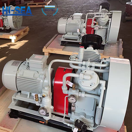
1.1 The cast, welded and machined surfaces on the outer surface of the air compressor shall be cleaned thoroughly, ensuring no rust, no scale and no welding slag. The painted surfaces shall be flat and smooth with uniform color. The paint shall be capable of preventing corrosion from salt spray, oil mist and moisture. For air-cooled air compressors, putty is not allowed to be applied on the outer surfaces of cylinders and cylinder heads; instead, heat-conductive paint with good thermal conductivity shall be used for spraying.
1.2 The air pipes, water pipes and oil pipes of the air compressor shall be painted in colors specified in GB 3033.1, and the arrangement of all pipelines shall be neat.
Overview
1. Appearance
1.1 The cast, welded and machined surfaces on the outer surface of the air compressor shall be cleaned thoroughly, ensuring no rust, no scale and no welding slag. The painted surfaces shall be flat and smooth with uniform color. The paint shall be capable of preventing corrosion from salt spray, oil mist and moisture. For air-cooled air compressors, putty is not allowed to be applied on the outer surfaces of cylinders and cylinder heads; instead, heat-conductive paint with good thermal conductivity shall be used for spraying.
1.2 The air pipes, water pipes and oil pipes of the air compressor shall be painted in colors specified in GB 3033.1, and the arrangement of all pipelines shall be neat.
1.3 Exposed fasteners and operating parts shall undergo decorative treatments such as bluing and chrome plating.
1.4 A nameplate or label for indication shall be provided above or below the pressure gauge.
2. Design and Structure
2.1 The air compressor shall be equipped with a pressure gauge for indication. The pressure gauge may have waterproof or luminous display functions as required.
2.2 The crankcase shall be provided with a lubricating oil supply hole, an oil level gauge, an oil drain plug, an explosion-proof valve and a ventilation device on its top.
2.3 In the cooling system of a water-cooled air compressor, parts in contact with cooling water shall be provided with rust and corrosion prevention measures, and a cooling water discharge passage shall be installed to facilitate water drainage from the cylinder.
2.4 A water-cooled air compressor shall be equipped with a cooler; water-cooled air compressors with multi-stage compression shall be equipped with an inter-cooler and an after-cooler. The cooler shall be provided with a cooling water safety valve or a safety diaphragm, as well as a drain cock or a drain valve. A small fusible plug or an alarm device shall be installed at the outlet of the air compressor's after-cooler, which shall trigger an alarm when the air temperature exceeds 121°C.
2.5 The air compressor shall be equipped with an unloading mechanism. In cases where automatic control is adopted, a manually operable mechanism shall be provided.
2.6 The air compressor shall be equipped with a liquid-gas separator (air-cooled air compressors with a nominal volume flow rate not exceeding 24 m³/h may be exempted from this requirement).
2.7 The connections of the air pipes, water pipes, and oil pipes of the air compressor shall ensure sealing, facilitate disassembly and assembly, and be vibration-resistant.
2.8 When the exhaust port, cooling water inlet, and cooling water outlet of the air compressor are connected to external pipelines using a flange structure, the external flanges of the air compressor shall comply with the provisions of GB/T 2506 and GB/T 10746.
2.9 An air filter shall be installed at the air intake of the air compressor.
2.10 The automatic control devices of the air compressor are divided into two types: semi-automatic and fully automatic.
2.11 A protective cover mainly made of wire mesh or steel plate shall be provided for exposed moving parts.
2.12 The flywheel (pulley) shall undergo static balance correction.
2.13 To facilitate easy resetting of the air compressor head after it is disassembled from the prime mover, locating pins shall be used for positioning between the air compressor head and the common base, as well as between the prime mover and the common base.
3. Material
Recommended Main Materials | |
Application | Material Name |
Base | Structural Steel, Forged Steel |
Cylinder, Cylinder Head | Cast Iron, Bronze, Forged Steel |
Cylinder Liner | Cast Iron |
Piston | Cast Aluminum, Cast Iron |
Crankcase, Machine Body | Cast Steel, Structural Steel, Forged Steel, Cast Iron, Cast Aluminum |
Crankshaft | Forged Steel, Ductile Iron (Nodular Cast Iron) |
Connecting Rod, Piston Rod, Bolts, Nuts (Bolts and nuts refer to those for connecting rod) | Forged Steel |
All rubber parts in contact with lubricating oil or oil mist shall be made of durable rubber. | |