
Pre-Delivery Requirements and Inspection for Marine Axial Fans
Final factory inspection verifies whether the fan fully complies with the performance parameters specified in the contract and technical agreement (such as airflow, static pressure, rotational speed, power, noise, etc.). Inspection must confirm consistency between the data on drawings and the actual physical data.
Overview
Reason:
Any issues discovered during inspection (such as cosmetic defects, minor performance deviations, or incomplete documentation) may be addressed immediately by the manufacturer before shipment. This prevents issues from being discovered after goods arrive at the port or aboard the vessel, thereby avoiding time costs, rework freight expenses, and potential delays to shipbuilding or repair schedules.
The following outlines inspection requirements and procedures for marine axial fans. All fans manufactured by Chongqing Hi Sea Marine Equipment Co., Ltd. undergo the following inspections.
1. Requirements
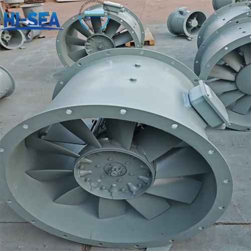
1.1 Appearance
The outer surface of the fan shall be clean and smooth, free from defects such as pressure marks, unevenness, or warping; welded areas shall be repaired to a smooth finish.

1.2 Dimensions and Weight
The dimensional tolerances of the fan shall comply with the m-grade specifications in GB/T 1804-2000. The weight shall not exceed ±5% of the specified value.
1.3 Design and Structure
1.3.1 General Requirements
1.3.1.1 The basic types, dimensional parameters, and performance curves of the fan series products shall comply with the provisions of GB/T 3235. The overall structure of the fan shall be airtight.
1.3.1.2 Both internal and external surfaces of the fan shall be coated with two layers of marine paint. Prior to applying the topcoat, the base layer shall undergo rust removal treatment and receive two coats of primer, in compliance with the coating specifications of JB/T6886. Fans manufactured from stainless steel may omit painting, but exposed stainless steel surfaces shall undergo polishing or passivation treatment.
1.3.1.3 Steel components of ventilation fans shall undergo galvanization with a coating thickness of no less than 0.045 mm. The corrosion resistance grade of selected steel materials shall not be lower than Grade B as specified in GB 8923-1988. Blast or shot blasting rust removal shall achieve Sa3 grade as specified in GB8923-1988. Manual and power tool rust removal shall achieve St3 grade as specified in GB8923-1988.
1.3.1.4 Fans shall be constructed such that, when viewed from the motor end, the impeller rotates clockwise or counterclockwise. Reversible structures may also be manufactured.
1.3.1.4 Riveted and welded components of the ventilation fan shall comply with the provisions of JB/T10214.
1.3.2 Casing
1.3.2.1 The casing shall be cylindrical. It may be manufactured as a monoblock or with axial opening as required. When the impeller diameter exceeds 600 mm, the casing shall generally be equipped with lifting lugs and support feet.
1.3.2.2 The surfaces of the casing and flanges shall be flat and possess sufficient rigidity. Defects such as compression damage, unevenness, or warping are not permitted. Geometric tolerances shall not exceed the specifications in Table 1.
Table 1: Housing, Flange Geometric Tolerances
Impeller diameter | ≤500 | >500~800 | >800~1200 | >1200~2200 |
Radial tolerance | 1.5 | 2.0 | 2.5 | 3.0 |
Roundness | 0.8 | 1.0 | 1.5 | 2.0 |
Parallelism of the two flanges | 1.0 | 2.0 | 3.0 | 4.0 |
1.3.2.3 Depending on the motor requirements, an oil filling port for motor lubrication may be added to the casing.
1.3.3 Impeller
1.3.2.1 The runout at the outer diameter of the impeller shall not exceed the specifications in Table 2.
Table 2: Runout at the Outer Diameter of the Impeller
Impeller diameter | ≤500 | >500~800 | >800~1200 | >1200~2200 |
Radial runout | 0.8 | 1.2 | 1.6 | 2.0 |
1.3.3.2 The deviation between the installation angle of each section of the impeller blades and the static blade installation angle shall not exceed ±1°.
1.3.3.3 The tolerance for the chord length at the outlet end of any three adjacent impeller blades shall not exceed the specifications in Table 3.
Table 3 Tolerances for Chord Length at Outlet End of Adjacent Blades
Impeller diameter | ≤500 | >500~800 | >800~1200 | >1200~2200 |
Number of blades≤10 | 4 | 6 | 8 | 10 |
Number of blades>10 | 3 | 4 | 5 | 7 |
1.3.3.4 Technical requirements for impeller castings shall comply with GB/T 9438.
1.3.4 Inlet and Outlet
1.3.4.1 The hole spacing tolerance on inlet and outlet flange bores shall not exceed ±0.5mm.
1.3.4.2 Depending on operating conditions, the inlet shall be equipped with a converging collector to reduce vortex formation and a streamlined casing guide hood.
1.4 Performance
1.4.1 Static and Dynamic Balancing of Impellers
The balancing accuracy grade of fan impellers shall not be lower than G5.6.
1.4.2 Impeller Overspeed
After undergoing an overspeed test exceeding the rated speed by 20%, the dimensional deformation of the fan impeller shall not exceed 0.5‰. Inspect blades, rivets, and hubs for cracks or damage.
1.4.3 Operation
During operation at rated conditions, the fan shall run smoothly without abnormal phenomena such as rubbing, unusual noises, or severe vibration.
1.4.4 Aerodynamic Performance
The pressure value of the fan at rated flow rate shall not exceed the rated pressure value by -5% to +10%. The flow rate of a reversible fan during reverse rotation shall be greater than 60% of the forward rotation flow rate, with the pressure value at this time not less than 36% of the forward rotation pressure value.
1.4.5 Vibration
The pressure value of the fan at rated flow shall not exceed the rated pressure value by -5% to +10%. For reversible fans, the flow rate during reverse rotation shall be greater than 60% of the forward rotation flow rate, and the pressure value at this time shall not be less than 36% of the forward rotation pressure value.
1.4.6 Noise
The A-weighted sound pressure level of the fan at the specified flow rate shall not exceed 34 dB(A).
1.5 Environmental Adaptability
The fan shall operate reliably under the following conditions. During testing, the fan shall run normally without abnormal phenomena such as rubbing, unusual noises, or severe vibration.
a) Conveying corrosive gases including marine air containing salt spray and oil mist;
b) Temperature range: -25°C to +50°C;
c) Relative humidity not exceeding 95%;
d) Impacts;
e) Tilting and swaying;
f) Vibration.
2. Factory inspection items and sequence shall be in accordance with Table 4.
Table 4 Test Items and Sequence
Items | Inspection Items | Certificate testing | Factory Inspection | Required Chapter Number |
1 | Appearance | * | * | 1.1 |
2 | Dimensions and Weight | * | * | 1.2 |
3 | Static and Dynamic Balancing of Impellers | * | * | 1.4.1 |
4 | Impeller overspeed | * | # | 1.4.2 |
5 | Operation | * | * | 1.4.3 |
6 | Aerodynamic Performance | * | # | 1.4.4 |
7 | Vibration | * | # | 1.4.5 |
8 | Noise | * | # | 1.4.6 |
9 | Environmental Adaptability | * | —— | 1.5 |
Note: *Mandatory inspection items; #Negotiable inspection items; —Non-inspection items. | ||||