
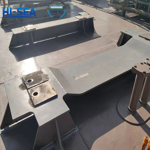
Welding Requirements for Windlass and Winch Foundations
The anchor windlass and marine winch foundation is the core load-bearing structure that withstands the dynamic loads of the windlass and winch, and its welding quality directly determines the operational safety of the anchoring equipment. Below is our summary of the welding requirements and precautions for windlass and winch foundations.
Overview
1. Pre-Welding Requirements and Precautions
1.1 Quality Control of Base Metals and Welding Consumables
The base metal shall be marine high-strength structural steel, and a classification society approved material certificate shall be provided. The surface of the base metal shall be free from cracks, blowholes, oil stains, rust, and scale; any defects exceeding the allowable limits shall be removed by grinding.
Welding consumables (electrodes/welding wires/fluxes) shall be strength-matched to the base metal and accompanied by classification society approval certificates. Electrodes shall be dried in accordance with the manufacturer’s instructions, and immediately stored in an insulated container for on-demand use after drying to prevent moisture absorption.
1.2 Groove Preparation and Assembly Requirements
The groove form, angle, root face, and assembly gap shall comply with the requirements specified in the Welding Procedure Specification (WPS) and construction drawings to ensure full penetration of the weld seam.
The assembly gap between the foundation and the deck (support structure) shall be uniform. If the local gap exceeds the allowable limit, it shall be adjusted by build-up welding followed by grinding. The filling of iron blocks is strictly prohibited. The horizontal deviation of the foundation shall be controlled within ≤1mm/m, and the vertical deviation within ≤1.5mm/m.
The same welding consumables as those used for formal welding shall be adopted for tack welding. The weld length shall be 50~100mm with an interval of 200~300mm. Tack welds shall be free from cracks and blowholes; any defective sections shall be completely removed before re-welding is performed.
1.3 Requirements for Welding Equipment, Personnel and Environmental Conditions
The welding equipment shall be of stable performance, with accurate current/voltage adjustment and reliable earthing. For gas metal arc welding (GMAW), the purity of the shielding gas shall be not less than 99.5% for CO₂ or comply with the specified mixture ratio for Ar+CO₂ blended gas.
The welding operators shall hold classification society approved welder certificates, which shall cover the welding process, base metal grade, and applicable plate thickness range.
The welding ambient temperature shall be not less than 5℃. If the temperature is below 5℃, preheat the area 100mm wide on both sides of the groove to a temperature range of 80~150℃. For outdoor welding operations, wind and rain protection measures shall be implemented. When the wind speed exceeds 8m/s (for GMAW) or 10m/s (for shielded metal arc welding, SMAW), a wind shelter shall be installed. Welding operations shall be suspended when the relative humidity exceeds 90%.
2. Welding Process Control
2.1 Strictly implement the welding parameters (current, voltage, welding speed, and interpass temperature) in accordance with the classification society approved WPS. For multi-layer and multi-pass welding, clean the slag after each layer is welded, and conduct a defect inspection before proceeding to the next pass.
2.2 Adopt symmetrical welding methods (diagonal welding, segmented back-step welding) to minimize welding deformation. Arc striking on non-welded areas of the base metal is strictly prohibited. If defects such as porosity or slag inclusions are found during welding, stop welding immediately, remove the defective sections completely, and then resume welding.
2.3 Control the interpass temperature within the range of 80~200℃ to prevent grain coarsening or the formation of cold cracks.
3. Post-Welding Treatment Requirements and Precautions
3.1 Post-Welding Stress Relief Treatment
The windlass and winch foundation shall undergo overall or local stress relief heat treatment: heat to 550~620℃ by electric heating or flame heating. The holding time shall be calculated based on the plate thickness (1 hour per 25mm of thickness). The cooling rate shall be ≤150℃/hour, and natural cooling shall be adopted after cooling down to below 200℃.
For local heat treatment, the heating range shall be ≥150mm on both sides of the weld seam. A temperature measuring instrument shall be used to monitor the temperature uniformity.
3.2 Weld Surface Cleaning and Finishing
After welding, remove the slag and spatter from the weld surface. Grind the weld surface with an angle grinder to ensure a smooth transition between the weld and the base metal. The weld reinforcement shall be controlled within the range of 0~3mm; excessive reinforcement shall be ground flat.
Remove surface defects such as undercuts, weld overlays, and depressions. The undercut depth shall be ≤0.5mm, and the length of continuous undercuts shall be ≤100mm.
3.3 Post-Welding Non-Destructive Testing (NDT)
Testing Scope: 100% non-destructive testing shall be performed on the butt welds and fillet welds of the foundation. The specific testing method shall be implemented in accordance with the drawings and specifications.
Testing Methods:
Ultrasonic Testing (UT) is preferred for detecting internal defects;
Radiographic Testing (RT) shall be used for rechecking the suspicious areas identified by UT;
Magnetic Particle Testing (MT) or Penetrant Testing (PT) shall be additionally performed on fillet welds to detect surface and near-surface defects.
3.4 Re-inspection of Dimensional Accuracy
After welding, re-measure the foundation’s levelness, verticality, and the deviation of the installation reference line. If the deformation exceeds the tolerance, flame straightening (600~800℃) or mechanical straightening shall be adopted. Forcible straightening at low temperatures is strictly prohibited.

1. Welding
1.1 Pre-Welding Preparation
1.1.1 Before welding, oxides, moisture, oil stains, and other contaminants that may affect welding quality shall be removed from the surface of the weld joint edges within a zone of at least 25 mm from the groove.
1.1.2 Tack welds and edge defects that may affect welding quality shall be removed before welding.
1.1.3 Low-hydrogen or ultra-low-hydrogen welding materials shall be used for welding air bottles. Regular testing and inspection shall be carried out in accordance with the manufacturer's instructions for the welding materials.
1.1.4 Misalignment between the two plate surfaces of butt welds on air bottles shall not exceed 10% of the plate thickness at any point. For longitudinal seams, the misalignment shall not exceed 3 mm; for circumferential seams, it shall not exceed 4 mm.
1.2 Welder Qualification and Welder Marking
Shall comply with the relevant provisions of GB 11038.
1.3 Welding Environment and Welding Procedure Qualification
Shall comply with the relevant provisions of GB 11038.
1.4 Welds
1.4.1 Weld surfaces shall be uniform and dense, free from cracks, weld spatter, pores, slag inclusions, undercut, arc craters, incomplete filling, lack of penetration, lack of fusion, or other visible defects. Any such defects shall be removed before non-destructive testing. Spatter on both sides of the weld must also be removed.
1.4.2 Weld surfaces may be flush with the base metal or slightly thicker at the center of the weld, but the transition in the weld reinforcement shall be gradual. The weld shall not have a flat or sharp-angled profile.
1.4.3 After surface defects or mechanical damage are removed by grinding, the thickness of the weld shall not be less than the negative tolerance thickness of the base metal.
1.4.4 Cross-shaped welds are not permitted in the assembly welding of air bottle cylinders. The distance between the longitudinal welds of the head and the cylinder section or between two cylinder sections shall not be less than 200 mm.
1.4.5 If unacceptable defects are found in a weld, they shall be repaired after removal. The number of repairs at the same location shall not exceed two. After repair, X-ray inspection and heat treatment shall be performed as required.
1.4.6 For single-side welding, appropriate measures shall be taken to ensure complete penetration at the weld root and to minimize deformation caused by shrinkage of the weld metal.
1.5 Welding Test Plates
1.5.1 The material grade and thickness of the welding test plates for air bottles shall be the same as those of the cylinder. The groove of the test plate shall be identical to that of the cylinder weld.
1.5.2 Test pieces are generally not required for circumferential seams. However, if the cylinder has only circumferential seams or if the processes used for circumferential and longitudinal seams differ significantly, one simulated test piece for the circumferential seam shall be welded.
1.5.3 The welding of test plates shall employ the same method, procedure, heat treatment, and the identical electrodes, welding wires, and fluxes as used for the product welding. The test plates shall undergo heat treatment in the same furnace as the cylinder.
1.5.4 The product welding test plates shall be welded by the welder performing the product welding. After welding, the welder's and inspector's identification codes shall be permanently marked (e.g., stamped) on the test plates.
1.5.5 Test specimens required for air bottles shall be prepared and tested in accordance with the provisions of GB 11038.
1.5.6 The results of the product welding tests for air bottles shall conform to the requirements specified in Table 4 of GB 11038.
1.6 Non-Destructive Testing
1.6.1 The scope of non-destructive testing shall comply with the stipulations in the following table.
Scope of Non-Destructive Testing
Testing Method | Pressure Vessel Class | |
Class I | Class II | |
Where P, δ, t are all less than the limits specified for Class I, but either P > 1.57, δ > 16, or t > 150 | Where P ≤ 1.57 and δ ≤ 16 and t ≤ 150 | |
Radiographic Testing (X-ray) | Welds of the test plate shall undergo 100% inspection. For product welds, a spot check of no less than 10% shall be performed. | — |
Magnetic Particle or Penetrant Testing | For welds on components such as pipes, columns, reinforcement plates, stubs, and branch pipes that have not undergone radiographic inspection, a 10% spot check by magnetic particle or penetrant testing shall be performed. | — |
1.6.2 For air bottles classified as Class II pressure vessels, the test plates may be exempted from X-ray radiographic inspection. However, the test plates for the initial product shall undergo 100% X-ray radiographic inspection in accordance with the requirements for Class I pressure vessels.
1.6.3 For low-pressure air bottles falling under GJB 14.1A, the test plates shall undergo 100% radiographic inspection.
1.6.4 For medium-low pressure air bottles falling under GJB 14.1A, more than 25% of the longitudinal butt welds and more than 15% of the circumferential welds shall undergo radiographic inspection. Film evaluation shall be performed according to GB 3323. The weld quality for longitudinal seams shall meet at least Class I, and for circumferential seams, at least Class II.
1.6.5 For air bottle products classified as Class I pressure vessels, the evaluation of butt weld radiographs shall be performed according to GB 3323. The weld quality for longitudinal seams shall meet at least Class I, and for circumferential seams, at least Class I.
1.6.6 When a head is fabricated by splicing several steel plates, at least 10% of the welds shall undergo X-ray radiographic inspection before forming. After forming, 100% radiographic inspection shall be performed. Film evaluation shall be conducted according to GB 3323. The weld quality for longitudinal seams shall meet at least Class I, and for circumferential seams, at least Class I.
1.6.7 For air bottles subjected to partial inspection, the manufacturer remains responsible for the quality of the untested portions.
2. Heat Treatment
2.1 Cold-formed heads must undergo normalizing heat treatment and non-destructive testing.
2.2 The following air bottles may be exempted from post-weld heat treatment:
a) Air bottles classified as Class I pressure vessels, when made of carbon steel with a welded component thickness of less than 30 mm and an operating temperature not exceeding 150°C; or when made of carbon-manganese steel with a welded component thickness of less than 20 mm and an operating temperature not exceeding 150°C.
b) All air bottles classified as Class II pressure vessels.
2.3 For air bottles requiring overall heat treatment, if overall treatment is impractical due to limitations, segmented heat treatment is permitted, provided the entire length of the weld seam is subjected to the heat treatment.
2.4 The temperature and holding time for the heat treatment of air bottles shall comply with the provisions of GB 11038.