
Introduction to Marine Ventilation Accessories
Marine ventilation accessories primarily include fans, ventilator, fire dampers, ventilation grilles, ventilation pipes, air diffuser, and air vents.
Overview
Marine ventilation systems are mainly categorized into natural ventilation and mechanical ventilation. These systems regulate compartment air environments through natural or mechanical means to safeguard crew health, equipment operation, and cargo safety.
Mechanical ventilation primarily employs forced air exchange via fans, enabling controllable airflow rates. Fans are mainly categorized as axial flow fans and centrifugal fans.
Natural ventilation systems primarily utilize temperature differentials or wind speed variations to drive airflow. Key equipment includes ventilator, funnel-type wind caps, and skylights.
System piping must meet fire compartmentalization requirements. Ventilation openings on high-speed vessels should be located away from exhaust pipes and equipped with watertight closure devices.
Axial fan | Centrifugal fan | Inline fan | Damper |
| | | |
Fire damper | Ventilation grille | Mushroom head | Goose-neck ventilator |
| | | |
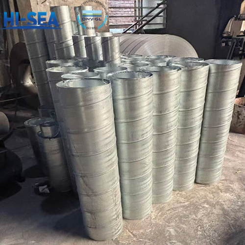
HVAC pipe | ventilation terminal | Air diffuser | Air vent |
| | |
|
The following are the technical requirements and test methods for ventilation accessories.
1. Technical Requirements
A. All ventilation accessories shall be free of burrs, sharp edges, and cracks. Surfaces shall be uniform and smooth.
B. Welded joints must be uniform and free of defects such as cracks, porosity, undercut, or spatter.
C. Steel ventilation accessories shall undergo rust removal treatment (either shot blasting or manual rust removal) and meet the Sa2 standard specified in GB8923.
D. Steel components requiring galvanization shall be treated according to CB/Z54, with a coating thickness of no less than 30μm. Aluminum parts shall undergo anodizing treatment per CB/Z92.
E. Moving parts of ventilation accessories, such as switches, lifting mechanisms, and rotating components, shall operate smoothly and effortlessly, with effective positioning or locking capabilities.
F. Friction points and rotating parts of all ventilation accessories shall be coated with lubricating grease.
G. Ventilation accessories designed for weather tightness, air tightness, or equipped with sealing devices shall maintain excellent sealing integrity. They shall undergo water-flushing tests, demonstrating no leakage after testing.
H. Fire dampers shall meet corresponding fire protection requirements of the SOLAS Convention and undergo fire resistance testing. They shall possess good insulation properties, voltage resistance, control opening/closing performance, and fire resistance, and function normally under various environmental conditions and operating states during vessel navigation.
I. Upon completion, products shall be coated with protective layers as required (including paint, galvanization, oxidation, etc.). Painted products shall receive one coat of topcoat either before shipment or after installation on board.
2. Test Methods
2.1 Hydrostatic Pressure Test
The hydrostatic pressure test shall be conducted in accordance with the test pressure requirements specified in Table 1. The test duration shall be 5 minutes.
Part | Pressure Test | ||
Body | Cutoff point | Sealing point | |
Ventilation gate valve | 0.15 | 0.1 | 0.1 |
Weather-tight, airtight cover | —— | Flush Test | —— |
Ventilator, ventilation head | —— | Flush Test | —— |
Damper with packing | —— | —— | 0.005 |
2.2 Flush Test
During the flush test, the nozzle diameter shall not be less than 12.5 mm, the water pressure shall not be lower than 0.25 MPa, the water jet distance shall not exceed 1.5 m, and the test duration shall be 3 minutes.
2.3 Fire Resistance Test
The fire resistance rating test for fire dampers shall be conducted continuously for 3 hours. Fire dampers equipped with a temperature fuse having a melting point of 70±3°C shall activate the temperature fuse within 60 seconds after the start of the fire resistance rating test or before the temperature reaches 141°C, thereby automatically closing the damper.
Chongqing Hi-Sea Marine Equipment Co.,Ltd Ventilation Products can meet all the above technical requirements and test methods.