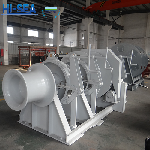
What is a hydraulic anchor windlass?
Hydraulic anchor windlass, also known as electric-hydraulic anchor windlass, is driven by an electric motor to drive a hydraulic pump, an oil motor, and then a gear-driven sprocket/chain wheel/gypsy shaft. There is a clutch between the sprocket and the transmission shaft. When it breaks down, the clutch is disengaged and the sprocket is controlled by the brake. The hydraulic anchor winch needs to be equipped with a hydraulic pump station, which can be used independently or in conjunction with other deck machinery such as cargo winches, mooring winches, cargo cover opening and closing mechanisms, etc.
Overview
Understanding principles
There are many types of hydraulic anchor windlass for ships. Taking a valve-controlled closed system hydraulic windlass using a quantitative blade pump and a two-stage variable blade oil motor as an example, the composition and working principle of its hydraulic system is shown in Figure 1-1.

The oil pump of the system adopts a double-acting fixed capacity vane pump, with a maximum working pressure of 6.86MPa. The oil pump is equipped with a safety valve f. The suction side of the pump is equipped with a magnetic filter F. The oil motor M adopts a double-acting vane type two-stage variable oil motor, which has a structure similar to that of a double-acting vane pump and is also composed of a stator, rotor, and vane. Vanes are installed in 8 evenly distributed blade slots on the rotor. To ensure that the vanes can closely adhere to the inner surface of the stator, rectangular section arc-shaped push rods are installed between every two vanes in the four arc-shaped slots on the rotor end face. During operation, the vanes are driven by pressure oil to rotate the rotor in the stator. Due to the rotor being connected to the shaft by keys, when the rotor rotates, it can directly drive the anchor chain wheel to rotate, thereby completing the task of lifting or dropping the anchor.
To achieve a compact structure and reduce the risk of pipeline rupture, the two control valves of the system are combined on the hydraulic motor, which has two valve chambers: one is the reversing valve chamber, which is equipped with a reversing valve and a one-way valve to control the forward, reverse or stop rotation of the oil motor; At the same time, it is also an open transition slide valve that can regulate the speed of the oil motor through parallel throttling. The other is the shift valve chamber, which is equipped with a shift valve. The low or high-speed working conditions of the oil motor can be controlled through the shift valve.
As shown in Figure 1-1b), when the directional handle is placed in the centre position, the directional valve is in the centre position and the bypass hole is opened. As a result, the pressure oil from the oil pump directly returns to the oil pump through the lower part of the directional valve. The system cannot establish sufficient oil pressure, and the one-way valve is closed. If the pressure oil cannot enter the oil motor, the oil motor stops.
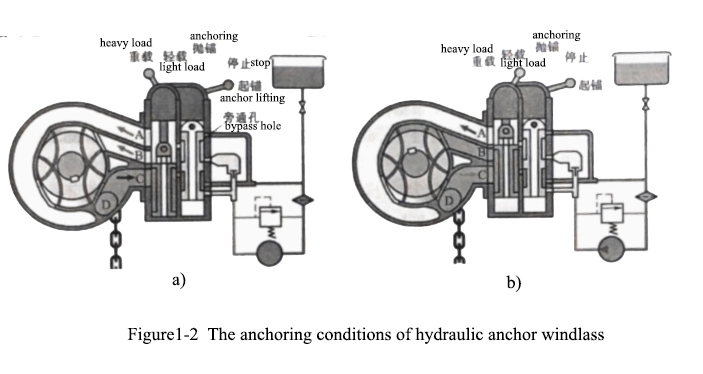
As shown in Figure 1-2a), pull the reversing handle backwards (anchor), and the reversing valve will move upwards, gradually closing the bypass hole 13. As a result, the oil pump's oil discharge pressure will increase, and the oil will push open the one-way valve. It will enter the oil motor through the reversing valve chamber and the shifting valve chamber for anchor lifting. At this time, the two chambers of the oil motor AB work simultaneously, so it is a heavy-duty low-speed working condition. If the shift valve handle is pulled to close oil passage B of the shift valve, pressure oil will only be able to enter the oil motor from oil passage A, and oil passage B will be connected to the return oil port, that is, the oil motor only has one rubber chamber working, which is a light load high-speed working condition, as shown in Figure 1-2b). At this point, the maximum output pulling force is only half of the heavy-duty working condition, but the speed is doubled compared to the former. Changing the operating angle of the reversing handle to control the flow of pressure oil into the oil motor can throttle and regulate the speed of the oil motor.
As shown in Figure 1-3a), pull the directional handle forward (anchor), and the directional valve will move downwards. As a result, the pressure oil from the oil pump will enter the oil motor through passage C, causing the oil motor to rotate in the opposite direction and anchor. The diagram shows the heavy-duty and low-speed operating conditions. Similarly, if the shift valve is moved up through handle 9, oil passages B and C will be connected, and the oil motor will obtain a light load high-speed working condition, as shown in Figure 1-3b). And the oil motor can also achieve throttling speed regulation by controlling the operating angle of the reversing handle 8.

The hydraulic oil in the overhead tank relies on the static pressure generated by gravity to maintain the suction pressure of the oil pump and replenish the system. The speed limit of this type of anchor can be regenerated by the closed system itself (feedback energy to the oil pump), and the energy consumption speed limit can also be achieved by controlling the directional control handle for throttling. During the lifting and anchoring process, if the handle is returned to the centre, hydraulic braking can be carried out, and the safety valve of the oil motor is equivalent to the brake relief valve. In addition, there is a manual brake handle to control the belt mechanical brake next to the cable lifter/gypsy/chain wheel/sprocket.
For more marine anchor windlass information, kindly please click here.

