
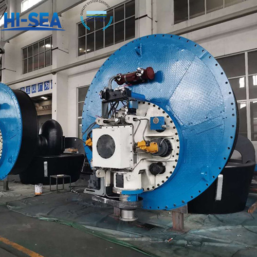
Type test of Z Propulsion Arrangement
A type test of a Z Propulsion Arrangement is an essential process to validate the design, performance, and safety of the propulsion system before it is approved for use in marine applications. This testing ensures that the system meets all relevant standards and operates reliably under various conditions.
Here’s an outline of what a typical type test might include:Visual inspection; Overall idling test; Pitch control test (where applicable); Functional test of alarm/safety; Tightness test; Gear engagement inspection;Safety valve/spill valve setting test; Turning test; Up-and-down/outward-swaying test (where applicable); Calibration test of zero rudder angle.
Overview
The following test requirements are based on CCS standards:
1 Selection of typical sample
The first product of the same type is to be type-tested.
2 Type test items are to include:
(1) Visual inspection;
(2) Overall idling test;
(3) Pitch control test (where applicable);
(4) Load test (where applicable)
(5) Hydraulic test of pressure element;
(6) Functional test of alarm/safety;
(7) Tightness test;
(8) Gear engagement inspection
(9) Safety valve/spill valve setting test;
(10) Turning test;
(11) Up-and-down/outward swaying test (where applicable);
(12) Calibration test of zero rudder angle (where applicable).
Whether the load test items are performed depends on the assessment conducted by CCS on the manufacturing works. If necessary, the product with a large power may be subjected to a part-load test with partial load reduced. On completion of installation on board, it is to be subjected to a test on board. The load test may be replaced by the on-board test data of the product of the same type.
3 Type test methods and requirements
(1) Visual inspection
① The components/parts such as upper/lower gearbox, rudder, shafting system and hydraulic system of the product are to be subjected to visual, integration and safety inspections.
② The components of the product are to be complete with intact and undamaged appearance, sound protective layer and tight fasteners.
③ The pipelines of hydraulic units are to be arranged regularly and bended smoothly; long pipelines are to be fixed; and flexible hoses are to be short as much as possible without abrupt bends or twisting
(2) Overall idling test
① Products without a propeller may be driven by the test device on the test bench at the manufacturing works for operation test.
② The rotation speed is to be gradually increased to the rated speed. The test is to last for at least 3 h.
③ The lubrication oil temperature of the gearbox is to be recorded during the test.
④ The system is to be able to work smoothly and steadily without abnormal noise and leakage.
(3) Pitch control test (where applicable)
① The Z propulsion arrangement with a controllable-pitch propeller is to be subjected to tests on pitch control time, pitch control stability, pitch control accuracy, pitch indication accuracy, etc.
② At the rated speed of the controllable-pitch propeller, the time required for the change of pitch angle from 1/3 positive maximum (or 1/3 negative maximum) to 1/3 negative maximum (or 1/3 positive maximum) is not to exceed 15 s.
③ The system is to work smoothly and steadily during the pitch control process. The
deviation between the pitch angle indicator and the actual pitch angle of the propeller is not to exceed ±1°.
(4) Load test
① The product may be driven by the test device on the test bench at the manufacturing works for load test.
② At the rated speed, the propeller blade is to be subjected to hydrodynamic and centrifugal loads simulating the propeller blade working condition.
③ The loads are to be gradually increased until the rated speed is achieved. The test is to last for at least 3 h
④ The working pressures of all oil pumps and cooling water pumps and the lubricating oil temperature and temperature rise of the gearbox are to be recorded during the test.
⑤ The temperature of the sliding bearing is not to exceed 70°C, and the temperature of the rolling bearing is not to exceed 80°C.
⑥ The system is to be able to work smoothly and steadily without abnormal noise and leakage.
(5) Hydraulic test of pressure element
The hydraulic and pneumatic pipelines are to be subjected to hydraulic tests to a pressure of 1.5 times the design pressure without leakage.
(6) Functional test of alarm/safety
① By the method of manually changing oil levels and oil (air) pressures and temperatures or manually analog input of faults, the alarm against such faults as low pressure of lubricating oil (if fitted with lubricating oil pump), high temperature of lubricating oil, low level of hydraulic oil, low pressure of hydraulic oil, high temperature of hydraulic oil (if fitted with oil cooler), too high pressure difference of hydraulic oil filter (if fitted with oil filter) and low pressure of clutch is to be inspected.
② Alarm values of the above-mentioned items are to meet the requirements of design plan.
③ All alarms are to be indicated in the bridge.
(7) Tightness test
① The components of Z propulsion arrangement such as upper/lower gearbox, steering gearbox and stem tube are to be subjected to a hydraulic test to 0.2 MPa on completion of fabrication and a tightness test on completion of assembly. The tightness test may be conducted with a liquid at a pressure of 0.1 MPa or compressed air at a pressure of 0.03 MPa by the soap liquid application method. Leakage is not allowed.
② For the turning test of oil distributor sealed bearing, the amount of leakage and the temperature under specified pressure and rated speed are to be in line with those indicated in the approved plan.
(8) Gear engagement inspection
① The contact condition of gear pair is to be verified by uniformly applying a thin layer of pigment under appropriate load.
② The gear contact spots are not to be less than the value provided in Table 10.4.3.1 of Chapter 10, Part Three of CCS Rules for Classification of Sea-going Steel Ships.
(9) Safety valve/spill valve setting test
① Safety valves/spill valves in the system are to be subjected to setting tests by the method of changing the pressures of hydraulic and control systems.
② The set values of safety valves/spill valves are to meet the requirements of design plan.
(10) Turning test
① The steering system is to be respectively turned clockwise and counterclockwise under static and dynamic conditions (turning and non-turning condition) for 360° for five times on the test bench at the manufacturing works.
② The time and pressure of rudder movement and the lubricating oil temperature and temperature rise of the gearbox are to be measured during the test.
③ The time of rudder movement is to meet the requirements of design plan.
④ The temperature of sliding bearing is not to exceed 70°C, and temperature of rolling bearing is not to exceed 80°C.
⑤ The system is to be able to work smoothly and steadily without abnormal noise and leakage.
(11) Up-and-down/outward-swaying test (where applicable)
① The liftable/outward-swaying rudder propeller is to be subjected to an
up-and-down/outward-swaying test on the test bench at the manufacturing works.
② The liftable/outward-swaying components are to be able to operate flexibly, smoothly and steadily without abnormal noise.
③ The up-and-down travel and the maximum outward-swaying angle are to meet the requirements of design plan.
(12) Calibration test of zero rudder angle (where applicable)
The steering control system is to be zero-calibrated based on the mechanical zero with an error of ±1.8°.
For more azimuth thruster information, please click here.