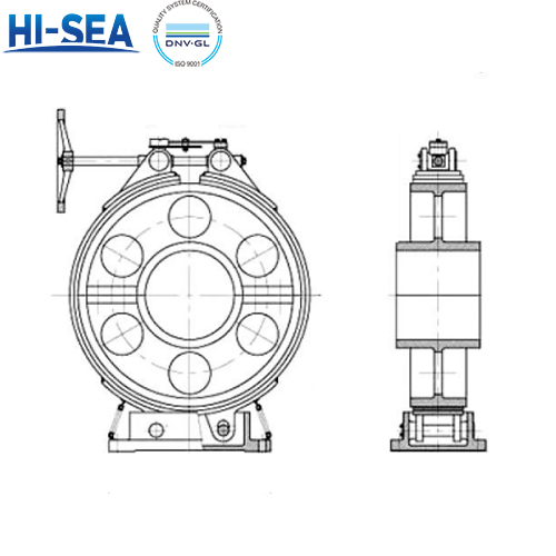
Technical requirements and performance of mechanical brakes for marine shaft systems
It is suitable for small and medium vessels whose stern shafts need to be locked when they anchor. According to the GB/T 35344-2017 standard, when producing marine mechanical brakes for marine shaft systems, its performance should meet the following requirements: Requirements for braking conditions: When the brake is in a tight state, the contact area between the brake band and the wheel should be greater than 80%, and the contact should be uniform. When the brake band is in a relaxed state, it should be completely released from the brake wheel and there should be no dragging or friction.
Overview
1. Appearance quality
The appearance of the axle brake should not have burrs, oxide skin, rust, oil stains, or dust.
The outer surface of the axle system brake should be coated with anti rust primer.
2. Material
Number | Parts name | Material | |
name | Material grade | ||
1 | Base | Carbon structural steel | Q235A |
2 | Spring | Carbon spring | 65Mn |
3 | Brake wheel | Gray cast iron | HT200 |
4 | Brake steel plate | High-quality carbon structural steel | 15Mn |
5 | Friction band | Steel fibre resin | — |
6 | Brake nut | Brass rod | H62 |
7 | Elastic signal device | Carbon structural steel | Q235A |
8 | Brake screw | High-quality carbon steel | 45 |
9 | Handwheel | Gray cast iron | HT200 |
3. Technical requirements
A. Requirements for braking conditions: When the brake is in a tight state, the contact area between the brake band and the wheel should be greater than 80%, and the contact should be uniform. When the brake band is in a relaxed state, it should be completely released from the brake wheel and there should be no dragging or friction.
Brake closing stroke: The closing stroke of the brake screw is controlled within the range of 140mm~300mm.
B. Technical requirements for brake bands:
The brake band composed of brake steel plate and friction band should meet the technical requirements of JB/T8817.
The friction band should be firmly riveted to the brake steel plate without any gaps. The friction band after riveting should be intact and undamaged, with slight cracks allowed.
There should be no cracking or peeling around the friction belt rivet hole. The coaxiality of the rivet head relative to the rivet rod should be 1.0 mm, and the riveting force of the rivet should be 6 kN~10 kN. After riveting, the rivet end should be flat, with less than 3 cracks allowed.
C. Friction band requirements: The thickness difference of the same friction band should not exceed 0.1 mm. When checking on the mold, both ends should be snug, and the gap between other parts should not exceed 0.1mm.
D. Welding requirements for steel plate connecting ring materials and steel strips: The forgings used for the connecting rings at both ends of the brake steel plate should comply with the provisions of JB/T 6031. The surface of the brake band welded parts should undergo acid pickling and phosphating treatment before welding in accordance with the provisions of GB/T 6807. The connecting ring welded parts with the steel plate should comply with JB/T5943, and the treated steel plate should be coated with anti rust primer.
E. Processing of brake parts: The processing of brake screws and nuts should comply with the provisions of GB/T 5796; The machined parts of other parts shall comply with the provisions of JB/T 5936.
F. Processing of brake parts: The processing of brake screws and nuts should comply with the provisions of GB/T 5796; The machined parts of other parts should comply with the provisions of JB/T5936.
G. Requirements for brake wheels: The material of brake wheels can be cast aluminum alloy. The flange of the shaft coupling in the cabin can replace the brake wheel.
4. Performance
Braking performance:
Safety: The stress on the stressed parts of the brake screw nut should not exceed 95% of its material yield strength, and the screw nut should be able to be used normally.
5. Inspection method
A. Dimensions: Use measuring tools to measure the dimensions of the shaft brake system.
B. Weight: Measuring the weight of the axle system brake with a measuring tool
C. Appearance measurement: visually inspect the appearance quality of the axle brake system
D. Materials: Check the materials and material certificates of each component.
E. Performance:
Braking performance: Place the brake on the test bench, thread the brake wheel into and fix it on the transmission shaft, so that the transmission is in a tight state. According to the technical agreement or design requirements, determine 1.2 times the torque value received by the propeller shaft when the ship is in a stopped or towed state as the applied torque. Using the balance force method, test the torque in the opposite direction of the applied torque and the measured torque, and the transmission shaft should not rotate.
Safety: Use the two ends of the tension testing machine fixture to respectively clamp the screw and nut of the brake screw nut assembly. The nut is equipped with a special nut collar fixture, and the inner diameter of the collar is greater than the major diameter of the thread. Calculate the contact area of the nut thread and the minimum yield force of the material used. After setting the tensile value (minimum yield force of 95%) on the tensile testing machine, start the tensile testing machine, uniformly load it to the set tensile value, keep it for 5 minutes, and then unload it. Take out the brake screw nut assembly and inspect whether the component thread has failed and the size changes.
For more marine shaft system components, kindly please click here.