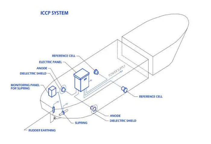
Arrangement of the Main Devices of the Impressed Current Cathodic Protection
Impressed current cathodic protection is a protection technology that uses a direct current power supply to apply a protective current to the hull through an auxiliary anode, so that the hull becomes a cathode and obtains polarisation and is protected from corrosion. The applied current cathodic protection on ships is still limited to the outer plate of the hull. Compared with the sacrificial anode protection, the primary investment of the applied current protection is higher and the installation is more complicated, but its service life is long, the protection effect is good, and it can be controlled automatically. Therefore, from the point of view of long-term protection, it is more favourable than sacrificial anode protection.
Overview
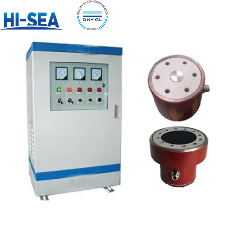
Marine Impressed Current Cathodic Protection System Device
Auxiliary anode for outputting anti-corrosion current;
Reference electrode for continuous determination of potential;
Constant potential meter which provides and can automatically control and adjust the low voltage direct current;
Anode shielding layer for extending the scope of protection: grounding device for propeller shaft and rudder.
Arrangement of Auxiliary Anodes
In the applied current cathodic protection system of the ship, the arrangement of auxiliary anodes should be symmetrical on the port and starboard sides, therefore, the number of anodes should be even. Therefore, the number of anodes should be double. 4~6 anodes are suitable for general ships, and the number of anodes for super-large ships (e.g. more than 200,000 tonnes) can be increased appropriately, but should not be more than 10 anodes.
The auxiliary anodes are usually arranged on the outer plate of the aft cabin area, and not arranged amidships as far as possible. For large ships with a length of more than 200 metres, one pair of anodes (or two pairs of anodes for ultra-large ships) is usually installed at the bow to make the current evenly distributed. The auxiliary anodes installed at the transom are mostly in the form of a long bar, and the bow is mostly in the form of a disc. No matter in the bow or in the transom, they should be installed below the ship's light-load waterline near the light-load waterline to ensure that the ship can be protected even in the light-load condition. For long strip arrangement, the horizontal direction should be taken. When two or more pairs of anodes are installed on the transom, the anodes should be spaced as far apart as possible.
Arrangement of Reference Electrodes
In principle, each constant potential instrument should be equipped with two reference electrodes (installed on the port and starboard sides respectively), and the position of the reference electrodes should be the position where the hull potential is at the average value. The reference electrodes are usually installed at a certain distance from the auxiliary anode (outside the anode screen) and at the same level as the auxiliary anode. If two pairs of auxiliary anodes are installed on the transom, the reference electrode should preferably be installed in the middle position of the two pairs of anodes.
Arrangement of Constant Potentialmeter
The rated output DC current of the potentiostat is relaxed according to the size of the total protection current, and two sets of potentiostats can be used if the rated output DC current of one set is not large enough. If both bow and stern are equipped with auxiliary anode, at least two sets of potentiostat should be used. The one on the stern is usually installed in the cabin, while the one on the bow is installed in the bow cabin or bow deck. Generally, the potentiostat is installed in a dry, ventilated place with less vibration and the ambient temperature is between -25~55℃.
