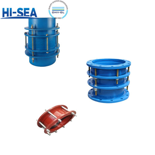
What is Compensator Joint?
Definition: Compensator Joint (Compensator Joint) is a special connector used in pipeline system to transmit axial thrust, compensate displacement and absorb vibration, the core structure includes double flanges, limit tie rods, sealing rings and other components.
Overview
Core function:
Transmission of thrust: the axial force generated by pumps and valves is transmitted to the overall structure of the pipeline to avoid equipment damage (such as water pump flange tear).
Compensate displacement: Allow pipeline thermal expansion and contraction or foundation settlement caused by ±15mm displacement (typical value).
Vibration and noise reduction: absorbs fluid shock vibration through rubber seals, reducing noise by more than 30% (e.g. water supply pipe network).
Differences with ordinary joints
comparison term | Compensator Joint | Ordinary flange joint |
Force characteristics | Can withstand axial tension/pressure | Transmission of medium pressure only |
displacement compensation | Supports axial/transverse displacement compensation | No displacement compensation capability |
Typical applications | Pumps and valves inlet and outlet, long distance piping | Conventional connections for straight pipes |
Main Types and Applicable Scenarios
typology | Structural characteristics | Typical Application Scenarios |
Single Flange Force Transmission Joint | One end flange + one end welding, easy installation | Pump room fixed end connections (e.g. fire pumps) |
Double Flange Force Transmission Joints | Double Flange Force Transmission Joints | Chemical pipeline pump valve import and export (need frequent maintenance) |
Detachable force transfer coupling | With loose flanges to allow fine tuning of pipe alignment | Underground Tunnel Settlement Zone Pipeline (Dynamic Adaptation to Deformation) |
Limit joints | Additional limit bolts to prevent over-limit stretch failure | Water supply risers for high-rise buildings (against seismic displacements) |
Selection of key parameters
Displacement: Calculated according to thermal expansion of pipeline (ΔL=α×L×ΔT, α is linear expansion coefficient).
Working pressure: conventional PN10-PN25, ultra-high-pressure type up to PN40 (need to strengthen the limit structure).
Media characteristics: acidic media priority EPDM rubber seals, high temperature steam with fluorine rubber.
Manufacturing process and quality control
1. Core manufacturing process
Body forming: Q235B steel plate rolled and welded, ring seam needs 100% X-ray flaw detection (RT test).
Seal processing: rubber sealing ring vulcanisation moulding, Shore hardness 55±5 (ASTM D2240 standard).
Limit assembly: High-strength alloy tie rod preload ≥ 1.5 times the working load (to prevent loosening).
Pressure test: 1.5 times the nominal pressure holding pressure for 30 minutes, leakage ≤ 0.1% is qualified.
2. Quality control points
Air tightness test: pressurise underwater to 1.25PN and observe the escape of air bubbles.
Fatigue test: no visible cracks on sealing surface after simulating 50,000 displacement cycles.