Type test of polymer bearings
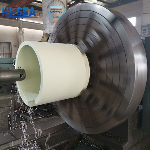
Polymer bearings are bearings made of polymer materials. Compared with traditional metal bearings, they have advantages such as light weight, corrosion resistance, low friction, and no lubrication. The type experiment of polymer bearings is to verify the performance and reliability of bearings in practical applications.
According to CCS rules, the type test of polymer bearings should include the following items: Compressive stress and compressive modulus of elasticity (25% strain), Tensile strength, Temperature resistance, Volume expansion in seawater, Volume expansion in oil, Seawater resistance, Linear expansion coefficient, Hardness, Impact strength, PV limit value, Density, Friction and wear test, etc.
Overview
1. Type test plan
Type test plan may be proposed by the applicant and approved by CCS, or presented by CCS and confirmed by
the applicant.
Type test plan is to cover at least the following aspects:
(1) Range of products for which the approval is being applied (type, specifications, delivery condition);
(2) Basis for type test plan;
(3) Type, specifications, quantity, delivery condition etc. of the typical samples selected for type test;
(4) Type test items and requirements for the tests;
(5) Sampling positions, schematic diagram and description;
(6) Recommended test organization;(7) Other aspects .to be indicated.
2. Selection of typical samples for type test
For initial recognition and approval modification, products of the maximum diameter and maximum thickness are
to be selected from the products within the scope of application as the typical samples for approval test.
3. Type testitems and requirements
Unless otherwise stated, the test specimens for various tests are to be arranged into groups consisting of at least fivepieces, and five effective test specimens within the same batch are to be ensured.
3.1 Compressive stress and compressive modulus of elasticity (25% strain)
(1) Shapes and dimensions of test specimens
① For fiber reinforced materials, the test specimens are to be in the shape of rectangular parallelepiped (type I) or cylinder (type II). The dimensions of test specimens are to be in accordance with the requirements in Table 3.1.
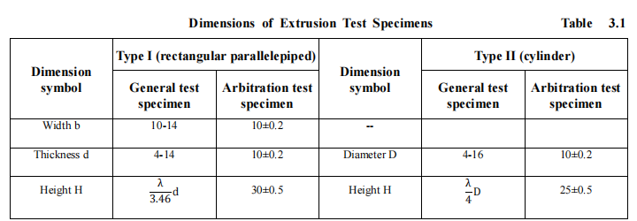
For type I test specimens, when the thickness d is less than 10mm, (10±0.2) mm is to be taken as the width b; when the thickness d is greater than 10mm, the thickness value is to be taken as the width b.10 is to be taken as the λ value when compressive strength is determined. Where instability happens during the test, 6 is to be taken as the λ value. λ is to be 15 or determined according to the readings of deformation measuring instrument when the compressive modulus of elasticity is determined.
① For other materials, the test specimens are to be in the shape of prism, circular cylinder or tube. The dimensions of test specimens are to comply with the inequation below:

ε*c—— the maximum nominal compressive strain occurring during the test, expressed by ratio;
x—— depends on the shape of the test specimen, diameter of circular cylinder, outer diameter of pipe or thickness of prism (minimum side of the cross-sectional area);
l——thickness of the test specimen measured along the direction parallel to the axis of compressive force.
Note: The ratio for measuring compressive modulus of elasticity is recommended to be x/l>0.08. The ratio for extrusion test is recommended to be x/l>0.8, which is equivalent to 25% of the maximum compressive strain.
③ The dimensional measurement of test specimens is to be accurate to 0.01mm.
(2) Test requirements
① For extrusion test of fiber reinforced materials, when modulus of elasticity is measured, v=2mm/min and when compressive strength is measured, v=1-6mm/min (v=2mm/min for arbitration test).
For extrusion test of other materials, when modulus of elasticity is measured, v=0.02l and when compressive strength is measured, v=0. 1l.
② Compressive modulus is to be calculated by the formula below:

Ec: compressive modulus, expressed in megapascal (MPa);
σ1: stress value measured at stress ε1=0.0005, expressed in megapascal (MPa);
σ2: stress value measured at stress ε1=0.0025, expressed in megapascal (MPa).
③ If the test specimen is not broken down during extrusion, the stress value corresponding to 25% of compressive stain is to be taken as the compressive strength of the material.
④ For fiber reinforced anisotropic materials, extrusion test is to be carried out along the direction in which the product bears the compressive force when the product is being used. Wheretheconsistence between such directions cannot be assured, the test is to be carried out along the two principal directions.
⑤ The test results are to meet the following requirements.Compressive strength: the direction of test for strip-shaped bearings is to be parallel to the extrusion face and the compressive strength is to be more than or equal to 85MPa; the direction of test for bearings of other shapes is to be vertical to the extrusion face and the compressive strength is to be more than or equal to 120MPa. Compressive modulus: compressive modulus is to be more than or equal to 1500MPa.
(3) Other requirements are to be in accordance with GB/T1041 Plastics-Determination of Compressibility (or ISO 604) and GB/T1448 Test Method for Compressibility of Fiber Reinforced Plastics (or ASTM D695) respectively.
3.2 Tensile strength
(1) Shapes and dimensions of test specimens
① The shapes of test specimens are as shown in Fig. 1 and Fig. 2.
.png)
.png)
.png)
② The dimensions of test specimens are to comply with the requirements of Table 3.2(1).
-Dimensions of Tensile Test Specimen.png)
Note:
①: for some materials, the length of the handle ends of test specimens need to be increased (e.g. 200mm) to avoid
fracture or sliding of the test specimen clipped by the grippers;
②: L3 = L0 + [4R(b1 − b) − (b1 − b)2]1/2
③: Where type I standard test specimens cannot be used for some reason, test specimens of type 1Ba, 1BB, 5A or 5B may be used;
④: Reference may be made thereto for test specimens of thickness less than 2mm.
③ The dimensions are to accurate to 0.01mm for type I and type II test specimens and to 0.02mm for the test specimens of other types.
(2) Test requirements
① Test velocity
The test velocity is to be 10mm/min for type I test specimens and 5mm/min for type II test specimens.
The test velocity for other test specimens is to be selected from Table 3.2(2) according to the recommendations of the manufacturer.
-Recommended Test Velocity.png)
② The tensile strength is to be more than or equal to 70MPa.
(3) Other test requirements are to be in accordance with ISO527-2 Plastics-Determination of Tensile Properties—Part 2: Test Conditions for Moulded and Extruded Plastics and GB/T1447 Test Method for Tensile Properties of Fiber Reinforced Plastics (or ISO527.4) respectively.
3.3 Temperature resistance
Compressive strength and compressive modulus of elasticity are to be measured after the test specimens have been heated to 50 °C and maintained at the same for an hour in accordance with the requirements of 7.3.1. The relevant test results are not to be less than 80% of the results obtained from tests at normal temperature. The test specimens are to be tested in 50 °C environment.
3.4 Volume expansion in seawater
(1) Each group is to include at least three test specimens which may be of tubular or plate strip shape and of 50×50×tmm dimensions. 4mm or the minimum thickness of the materials within the scope of application for approval is to be taken as the value of t.
(2) Test requirements
① Seawater is to comply with the requirements of ASTM D1141.
② Tests are to be carried out in 20 °C and 80 °C liquid environments respectively. The allowable deviation of test temperature is to be ±2 °C and soak time four weeks.
③ The volume of seawater is to be calculated according to the surface area of the test specimen and to be no less than 8ml per square centimeter.
④ The test specimen is to be fully soaked in seawater and a weight may be attached to the test specimen when necessary. The three test specimens of one group may be soaked in the same container; however, contact between the surfaces of the three test specimens or contact of the test specimens with the container wall and attached weight is not allowed.
⑤ The soaking seawater is to be agitated at least once every 24 hours and replaced once every 7 days.
⑥ The volumetric change rate of test specimens is to be measured at room temperature. If the soaking temperature is not equal to the room temperature, the test specimens may be rapidly transferred into and soaked in fresh seawater at room temperature for 15-30 minutes prior to the measurement.
⑦ The measured volume expansion ratio is not to be greater than 3%.
⑧ For the materials with applied surface pressures over 5.5N/mm², alternate wetting and drying soaking test at 20 °C is to be performed. With the four weeks’ soak time, the test specimens are to be soaked in the seawater for three days and placed in the air for three days, and then soaked again in the seawater for three days and placed in the air for three days, and so repeatedly in circles. The test is to start from three days of soaking and end at three days of soaking. The measured volume expansion ratio of test specimens till the end of the test is not to be greater than 3%.
(3) Other requirements are to be in accordance with ISO175 Plastics-Determination of Liquid and Chemical Agents Resistance
3.5 Volume expansion in oil (20 °C, four weeks)
The test specimens, test process and results are to be the same as those described in 3.4. Oils specified in ISO1817 are to be selected as the soaking medium according to the manufacturers’ requirements. Only the volume expansion ratio at the soaking temperature 20 °C is to be measured. Other requirements are to be in accordance with ISO175 Plastics-Determination of Liquid and Chemical Agents Resistance.
3.6 Seawater resistance (four weeks, compressive stress and modulus at 25% of strain)
After four weeks’ soaking in 20 °C seawater described in 7.3.4, the test specimens are to be removed from the seawater, dried and extrusion tested in accordance with 3.1 to measure the compressive strength and compressive modulus of elasticity. The test results are not to be lower than 80% of the results measured at normal temperature.
3.7 Linear expansion coefficient
(1) The test specimens are to be of a length within the range of 50mm~125mm and have circular, square or rectangular section to allow easy placement into the dilatometer and avoid excessive friction. The cross-sectional area of the test specimen is to be sufficient large to prevent bending and torsion. The section of the test specimen is normally12.5mm×6.3mm or 12.5mm×3mm in dimensions and 12.5mm or 6.3mm in diameter. The test specimen is to be cut even on both ends along the direction vertical to its long axis. Where the test specimen contract inside the dilatometer, smooth and thin iron or aluminum metal sheets are to be used to fix and position them in the dilatometer. The thickness of these metal sheets is to be within the range of 0.3mm~ 0.5mm.
(2) Test requirements
① Measure the two condition-adjusted test specimens using caliper to an accuracy of 0.02mm.
② Attach the iron sheets to the bottom of the test specimens to avoid contraction and re-measure the length of the test specimens.
③ Use the same dilatometer for all test specimens and place the same in -30 °C environment. If a liquid bath is used, it is to be ensured that the top of test specimens is 50mm below the liquid surface. Maintain the liquid bath temperature at a constant value of (-32~-28 °C) ±0.2 °C and wait to allow equilibrium of the temperature of test specimens with that of the constant-temperature bath. Record the measured temperatures and the dilatometer readings 5min~10min after the readings of dilatometer become stable.
④ Place the quartz dilatometer into -30 °C constant-temperature bath with care while avoiding vibration and
swaying. Repeat the operation of step ③.
⑤ Measure the final length of the test specimens at room temperature.
⑥ If the difference between the absolute values of expansion and contraction per degree centigrade of the
test specimens is greater than 10% of the average, the causes are to be analyzed and eliminated if possible.
Then the test is to be re-conducted until the requirements are met.
⑦ The average linear expansion coefficient per degree centigrade of the test specimens is to be calculated
by the formula below:

α——linear expansion coefficient, °C-1
∆L——arithmetic average of the expansion andcontraction of the test specimen, expressed inmm
L0——original length of test specimens, expressed in mm
∆T——average value of the temperature differences between two constant-temperature baths
The test results are expressed in the arithmetic average values of one test specimen group.
3.8 Hardness
(1) Brinell hardness is to be measured for the fiber reinforced materials. The thickness of the test specimens is to be no less than 1.5mm. The test specimens are to be sized to ensure a minimum distance of 3mm from any extrusion point to the edge of the test specimens and from one extrusion point to another. 10 tests are to
be performed when the hardness is more than or equal to 60, 16 tests are to be performed when the hardness is more than or equal to 50 and less than 60, 22 tests are to be performed when the hardness is more than or equal to 40 and less than 50 and 29 tests are to be performed when the hardness is more than or equal to 30 and less than 40. The arithmetic average values of the measurements of one test specimen group are to be taken as the final results. The test is to be carried out on the force bearing surface of the material.
(2) Rockwell hardness is to be measured for other materials. The thickness of the test specimens is to be no less than 6mm. The test specimens are to be sized to ensure a minimum distance of 10mm from any extrusion point to the edge of the test specimens and from one extrusion point to another. Each test specimen is to undergo at least five measurements. The Rockwell hardness value is to be within the range of 50~115 and values beyond this range are incorrect and to be re-measured using the adjacent gauge. The test is to be carried out on the force bearing surface of the material.
(3) Other requirements are to be in accordance with GB/T3398.2Plastics-Determination of Hardness—Part 2: Rockwell Hardness (or ISO2039.2) and GB/T3854 Test Method for Barcol Hardness of Reinforced Plastics (or ASTM D2583) respectively.
3.9 Impact strength
Impact test is to be carried out in compliance with the requirements of GB/T1043.1 Plastics-Determination of Charpy Impact Properties Using Simply Supported Beams–Part 1 Non-instrumented Impact Test (or ISO179) and GB/T7984 Method for Testing Impact Toughness of Fiber Reinforced Plastics Composites Using Simply Supported Beam respectively.
3.10 PV limit value
For materials intended to be used on stern shaft bearing, the PV limit value is to be measured in accordance with the specific requirements in GB7948 Test Method for PV Limit of Plastic Bearings.
3.11 Density
Density is to be measured in accordance with GBT1033.1 Plastics-Determination of the Density of Non-foamed Plastics–Part 1 Immersion Method, Liquid Pyknometer Method and Titration Method (or ISO1183.1).
3.12 Friction and wear test
(1) Friction factor is to be measured during the test and not greater than 0.25.
(2) The friction factor and wear rate of stern shaft bearings are to be measured in accordance with the requirements of GB/T3960.
(3) The tests for rudder bearings may be carried out with reference to the requirements stated below.
① The diameter of rocker shaft is to be 100mm;
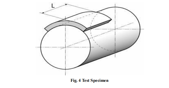
② The test specimen is to be part of the fixed bearing (see Fig. 4 for details) and to cover at least 50° circumferential range of the rocker shaft. The length of the bearing specimen is to be 1.2 times of the diameter of the rocker shaft (to be 80-120mm for shafts of 100mm in length) and the diameter of the bearing is to be 1mm more than that of the rocker shaft or in accordance with the manufacturer’s recommendations.
③ Artificial seawater is to be used for lubrication.
④ The swing amplitude of the rocker shaft is to be ±15°.
⑤ The test is to be carried out at the applied surface pressure and double applied surface pressure respectively.
⑥ The test may be carried out in dry state or artificial seawater lubricated state.
⑦ The ambient temperature is to be 20 °C.
⑧ The test velocity is to be 3.5mm/s.
⑨ The rocker shaft is to work continuously at the applied surface pressure. Prior to the test, upon the consent of CCS and taking into account the limit of PV value of the material, for the materials having a surface pressure higher than that being applied for, the test may be suspended for no longer than 10S each time when the rocker shaft passes the bearing center line.
⑩ The duration of the test is to be such that a stable wear rate is achieved (at least 192 hours at 3.5mm/s) or 850 hours at maximum (not including the time consumed by dismantlement and stops).
⑪The rocker shaft is to be made of stainless steel and have a maximum surface hardness of 220HV5. The surface roughness of the friction pairs is to be Ra=0.8µm.
⑫ The wear of the bearing or shaft is to be continuously or periodically measured. Where periodical measurement is adopted, the bearing or shaft is to be dismantled and measured once every 48 hours until a stable wear rate has been reached as demonstrated by four satisfactory measurements.
⑬ The relationship of wear loss to time and pressure, the relationship of wear loss to test cycle, the relationship of wear loss to travel distance and the relationship of friction factor (to be measured continuously or periodically to a stable wear rate at 20 °C) to time and pressure are to be demonstrated by charts.
⑭ To distinguish thermal expansion from the measured wear loss, thermocouples are to be used where necessary. Thermal expansion and expansion caused by immersion in water are to be taken into account when the wear data is determined.
⑮ For materials having an applied surface pressure not greater than 5.5N/mm², dry friction and wear test is to be carried out at 20 °C and 80 °C, at the applied surface pressure and at double applied surface pressure, under dynamic and static conditions respectively. The measurement of friction coefficient during the test is to comply with the requirements of article (1).
⑯ For materials having an applied surface pressure greater than 5.5N/mm², in addition to the test as required in ⑮, wet friction and wear test is to be carried out. The measurement of friction coefficient during the test is to comply with the requirements of article (1).
3.13 Where the requirements for the result limits of the abovementioned tests are not available, the related test results are to comply with the manufacturer’s specifications.
For more marine rudder system components, kindly please click here.

