
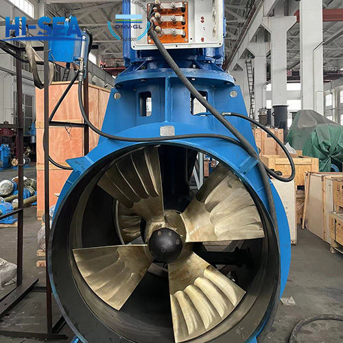
Type test of marine transverse propulsion arrangement
The type test of marine transverse propulsion arrangement refers to a series of tests and evaluations conducted during the design and manufacturing process of marine transverse propulsion arrangement to ensure that their performance and quality meet the design requirements and specifications.
Type test items are to include: Visual inspection; Dimensional inspection; Hydraulic test; Tightness test; Pitch control test (where applicable); Functional tests of safety protection and alarm; Other test items.
Overview
The following test requirements are based on CCS standards:
1 Selection of typical sample
1.1 The first product of the same type is to be type-tested.
2 Type test items are to include:
(1) Visual inspection;
(2) Dimensional inspection;
(3) Hydraulic test;
(4) Tightness test;
(5) Pitch control test (where applicable);
(6) Functional tests of safety protection and alarm;
(7) Other test items (The hydraulic power pack and electrical control box of controllable-pitch propeller are to be subjected to combined commissioning with the transverse propulsion arrangement for functional check. The hydraulic power pack of controllable-pitch propeller is to be tested according to Section 7, Chapter 2, Part Three of Rules for Classification of Sea-going Steel Ships.)
(8) Overall idling test (where applicable). For the overall idling test, the manufacturing works may apply to CCS for assessment. For the enterprises passing the assessment, the test may be replaced by other inspection methods.
3 Type test methods and requirements
3.1 Visual inspection
(1) The main components such as propeller, propeller shaft, drive/driven gear, drive shaft and equipment and connecting pipes of hydraulic system are to be subjected to visual inspection and feel test according to the plan requirements.
(2) The components of the product are to be complete with intact and undamaged appearance, sound protective layer and tight fasteners.
(3) The pipelines of hydraulic units are to be arranged regularly and bended smoothly; longpipelines are to be fixed; and flexible hoses are to be short as much as possible without abrupt bends or twisting.
3.2 Dimensional inspection
(1) The measured outline dimensions of drive shaft, propeller shaft, drive/driven gear and propeller blade are to be in line with those indicated in the approved plans.
(2) The measured gear contact area and backlash are to be in line with those indicated in the approved plan.
(3) The measured tip clearance between the propeller blade and the tunnel is to be in line with that indicated in the approved plan.
3.3 Pitch control test (if any)
(1) The transverse propulsion arrangement with a controllable-pitch propeller is to be subjected to tests on pitch control time, pitch control stability, pitch control accuracy, pitch indication accuracy, etc.
3.4 Hydraulic/tightness test
(1) Before being assembled, the pipelines and pressure elements of hydraulic transmission system and control system for controllable-pitch propellers are to be subjected to hydraulictests to a pressure of 1.5 times the working pressure. Before the tightness test, the pipelines of hydraulic transmission system and control system for controllable-pitch propellers are to be oil-flushed. On completion of assembling, the pipelines and pressure elements of hydraulic transmission system and control system for controllable-pitch propellers are to be tested to 1.25 times the working for tightness. The fixed sealing parts and pipe joints are free of leakage.
(2) The gearbox of transverse propulsion arrangement is to be subjected to a hydraulic test to 0.2 MPa on completion of fabrication, and a tightness test on completion of assembling. The tightness test may be conducted with a liquid at a pressure of 0.1 MPa or compressed air at a pressure of 0.03 MPa by the soap liquid application method. The test is to last for at least 5 min. Leakage is not allowed.
(3) For the turning test of oil distributor sealed bearing, the amount of leakage and the temperature under specified pressure and rated speed are to be in line with those indicated in the approved plan.
3.5 Functional test of alarm/safety
(1) Alarm required in the bridge with individual or groupwise indicators for the following faults is to be inspected:
Stop of prime mover;
Power failure of remote control system;
Failure of alarm system;
Low level in lubrication oil tank (if fitted);
Low lubrication oil pressure (if forced lubrication oil system);
Low level in hydraulic supply tank (applicable to transverse propulsion arrangements with a controllable-pitch propeller);
Low pressure in hydraulic system (applicable to transverse propulsion arrangements with a controllable-pitch propeller);
(2) The following individual indication items required in the bridge are to be inspected:
Overload of prime mover or servo unit;
Propeller pitch for controllable-pitch propeller plants;
Direction of rotation and r.p.m for fixed propeller plants;
Power failure of alarm system;
(3) For transverse propulsion arrangements for ships to apply for CCS class notation for dynamic positioning, the following alarm or indication items in the control station are to be inspected:
Transverse propulsion speed (for fixed pitch propeller);
Transverse thrust direction;
Coolant leakage of transverse propulsion motor/thyristor inverter;
Temperature of transverse propulsion motor/thyristor inverter;
Short circuit of transverse propulsion motor;
Excitation power supply for transverse propulsion motor (applicable to DC motor);
Power supply for transverse propulsion motor;
Thrust in %.
If the above required alarm and indication items are impractically or unnecessary to be arranged, or have equivalent arrangements, with the consent of CCS, the number of items may be reduced based on the actual situation.
3.6 Overall idling test
(1) Products without a propeller may be driven by the test device on the test bench at the manufacturing works for operation test.
(2) The rotation speed is to be gradually increased to the rated speed. The test is to last for at least 3 h. The test time of controllable-pitch propeller may be correspondingly reduced. If necessary, a test on board may be conducted.
(3) The working pressures of all oil pumps and the lubrication oil temperature of the gearbox are to be recorded during the test.
(4) The system is to be able to work smoothly and steadily without abnormal noise and leakage.
3.7 Other tests
(1) See Chapter 10 “Copper Alloy Propeller” of Part Two of CCS Guidelines for Product Inspection for the type test of propeller.
(2) See guidelines for electrical control system of controllable-pitch propeller for the type test of electrical control system.
For more marine bow/tunnel thruster information, please click here.