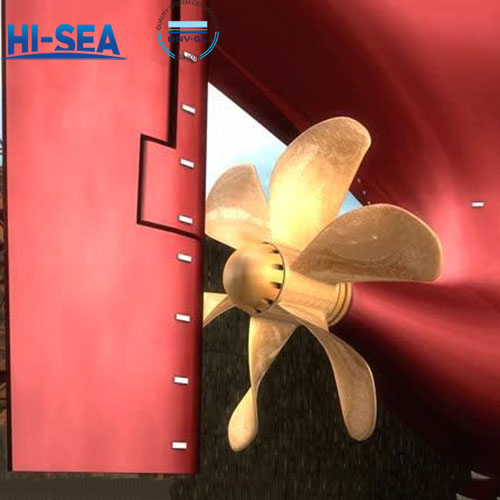
Type test of marine propellers
The type test of marine propellers refers to a series of tests and evaluations conducted during the design and manufacturing process of marine propellers to ensure that their performance and quality meet the design requirements and specifications.
Common experimental projects include: Chemical composition analysis, Metallographic examination, Mechanical property test, Visual, dimensional and geometrical tolerances examination, Non-destructive test, Pressure test, Weighing test, etc.
Overview
The following test requirements are based on CCS standards:
1 Selection of typical samples
The selection of typical samples for works approval is based on the following requirements:
(1) The typical samples are selected according to the types of copper alloy material, in which Cu3 may cover Cu4, and Cu1and Cu2 may cover each other.
(2) The diameter of at least one alloy typeof propellers is to be more than 90% of the maximum diameter of the products for approval, or the mass more than 80% of the maximum mass of the products declared by the manufacturer.
(3) Products manufactured by complicated technology are preferably selected.
Note: The restrictions specified in this clause can be relaxed for the renewal of the WorksApproval Certificate.
2 Type test
The type test items and results are to be carried out according to the following requirements. The typical samples are to be cast according to the requirements in 9.1.5, Section 1, Chapter 9, PART ONE of CCS Rules for Materials and Welding.
(1) Chemical composition analysis: The melting analysis and the chemical composition analysis of product should be carried-out. The chemical composition of product is to comply with the requirements in 9.1.3, Section 1, Chapter 9, PART ONE of CCS Rules for Materials and Welding.
(2) Metallographic examination: the metallographic examination is applicable to propellers made of Cu1 and Cu2. At least one specimen is to be taken from each heat, and the proportion of α phase is to be determined as the average value of 5 counts. The test results are to comply with the requirements in 9.1.3, Section 1, Chapter 9, PART ONE of CCS Rules for Materials and Welding.
(3) Mechanical property test: round proportional tensile test specimens with diameter of 14mm are to be cut from each test sample in accordance with the requirements given in Item 2 of Table 2.2.2.1 in Chapter 2 of PART ONE of CCS Rules for Materials and Welding. The tensile strength, 0.2% proof strength and elongation are to be determined by mechanical property tests. The test results are to comply with the values given in Table 9.1.6.3, Section 1, Chapter 9, PART ONE of CCS Rules for Materials and Welding.
(4) Visual, dimensional and geometrical tolerances examination: the external quality is to comply with the requirements given in CCS Rules for Materials and Welding. The
dimension, dimensional and geometrical tolerances and surface roughness are to be in accordance with the drawings approved by CCS. Where it is not specified, the requirements given in ISO484 Shipbuilding-Ship screw propellers-Manufacturing Tolerances or GB 12916 Specification for marine metallic propeller apply.
(5) Non-destructive test: each propeller and its components are to be subject to NDT according to ISO3452-1:2013 or the standard approved by CCS in accordance with the relevant requirements in Section 4, Chapter 8 of PART THREE of CCS Rules for Materials and Welding. All propeller castings are to be subject to dye penetration inspections in accordance with three zones A, B, and C. The inspections of Zone A are generally to be carried out in the presence of the Surveyor. Inspections of Zones B and C are to be performed by the manufacturer and a test report is to be submitted to the Surveyor for confirmation, or may be witnessed by the Surveyor as he requires. The NDT results are to comply with the requirements given in Section 4, Chapter 8 of PART THREE of CCS Rules for Materials and Welding.
(6) Static balancing: static balancing test is to be carried out on all propellers.
① When the propeller subjected to static balancing test is setupright on horizontal type static balancing equipment , indifferent equilibrium test is to be carried out first, then followed by weighing test. The frictional moment of the core shaft of static balancing equipment is not to exceed:

The calculated weight suspending is to be in accordance with the drawings approved by CCS. Where it is not specified, the following value is to be taken (whichever is lesser):

The coefficient C ,K is given in the following Table 8(1).
 Coefficient k value.png "Table 8(1) Coefficient k value.png")
Remark:
As the rated running speed of the propeller going up,the calculation outcome according to the above mentioned formulae is to become smaller infinitely,when the calculation outcome as the criterion for weight suspending is difficult to overcome the static friction force, the criterion for weight suspending can be enlarged properly,but should not be greater than 20g.
② When the propeller subjected to static balancing test is placed on upright static balancing equipment ,the unbalance mass measured (the total additional bob-weight which are attached to max. thickness gauge points of one or more blade tips in order to achieve equilibrium) should not greater than the value which equals to 1/2multiplies the calculation outcome according to the above mentioned formulae ,where Xn is hub diameter ratio
Where the works is to manufacture only the components (such as blades)of built-up
propellers (such as controllable pitch propeller) without fabrication, and the shipbuilder responsible for fabrication has no static balancing conditions, each blade is to be subject to moment balancing test in the works to determine the balancing moment of gravity center of the blade to propeller axis. For controllable pitch propeller with four blades, the balancing moment of each blade to propeller axis is to meet the following formula:

The coefficient f is to be taken according to the following Table 8(2):
 Coefficient f value.png "Table 8(2) Coefficient f value.png")
(7) Dynamic balancing: dynamic balancing is generally required for propellers running above 500rpm,and the permissible unbalanced moments are to comply with the drawings approved by CCS. Where it is not specified, the remaining unbalance mass of propellers are not to exceed the value uper calculated by the following formula:

(8) Pressure test: the components of built-up propellers with hydraulic fluid cylinders are to besubject to pressure test during products survey. The test pressure is to be in accordance with the drawings approved by CCS. Where it is not specified, 1.5 times the working pressure apply.
(9) Weighing test: propellers are to be weighed and recorded. The mass tolerance of the first finished product of propeller is generally not to exceed ±4% of the theoretical massaccording to three dimensional model calculation. The mass of the second and the subsequent products are determined according to that of the first finished product of propeller, and the mass difference is generally not to exceed ±2% of the above mentioned theoretical mass.
(10) Repairs of defects: the repairs of propellers are to comply with the requirements in Section 4, Chapter8, PART THREE of CCS Rules for Materials and Welding. Where the propellers have defects in Table 2 subject to weld repair, a detailed welding procedure specification and areas of repairs are to be submitted to CCS for approval, covering the weld preparation, welding procedure, filler metals, preheating, post-heating and inspection. The welding procedure is to be approved by CCS in advance. Detailed requirements are given in Tables7(3), 7(4) and 7(5).
 Recommended filler metals and heat treatment temperatures.png "Table 7(3) Recommended filler metals and heat treatment temperatures.png")
 Weld repair region and area.png "Table 7(4) Weld repair region and area.png")
 Stress relief treatment time for copper alloy propellers.png "Table 7(5) Stress relief treatment time for copper alloy propellers.png")
Where defects exist in typical samples and weld repair is feasible, the weld repair and stress relief heat treatment for specific defects are to be deemed as type test items. Where the welding quality is found unsatisfactory (such as cracks or openings with size over 3mm) in the test, the test fails. The inspection of weld repair is to be carried out in accordance with 8.4.8, Section 4, Chapter 8, PART THREE of CCS Rules for Materials and Welding.
For more marine propeller information, kindly please click here.