The transmission form of ship propulsion
To meet the requirements of different ships and navigation areas, the structure and form of propulsion facilities in ship power devices are different. Here is a brief introduction to several common types of ship propulsion transmission and their equipment: direct transmission, indirect transmission, electric transmission, Z-type transmission, and controllable pitch propeller transmission.
Overview
To meet the requirements of different ships and navigation areas, the structure and form of propulsion facilities in ship power devices are different. Here is a brief introduction to several common types of ship propulsion transmission and their equipment: direct transmission, indirect transmission, electric transmission, Z-type transmission, and controllable pitch propeller transmission.
For more marine shaft system information, kindly please click here.
For more marine shaft system components, kindly please click here.
1. Direct transmission
Between the main engine and the propeller, in addition to the transmission shaft system, in equipment with no other transmission power, this transmission form is called direct transmission. As shown in Figures 1-2.
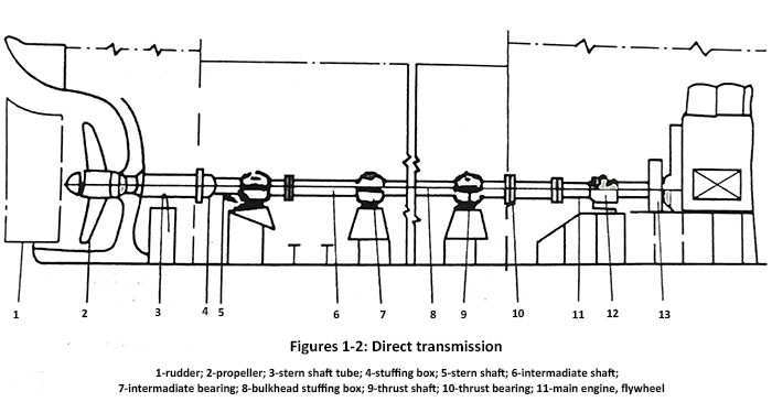
The characteristics of direct transmission: high transmission efficiency and good economy. Currently, many ships around the world adopt this type of transmission. At present, Chinese shipyards use this transmission method to manufacture oil tankers and cargo ships with a capacity of over 10000 tons.
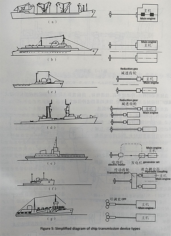
Most of these types of ships use large and medium-sized high-power low-speed and medium speed diesel engines, which have low fuel consumption and can directly drive the propeller to rotate, which is the fundamental reason for good economic reliability. But this type of transmission type makes the size index of the main engine very high, and the diameter of the propeller itself is usually relatively large, so it is suitable for use in marine vessels, as shown in Figure 1-5 (a) and (b).
2. Indirect transmission
As shown in Figures 1-3, in addition to the transmission shaft system, devices such as a reduction gearbox and clutch are also installed between the main engine and the propeller, which we refer to as indirect transmission type.
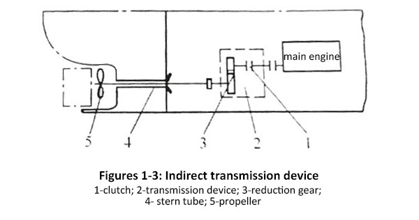
When using a high-power steam turbine as the main engine, a transmission gear mechanism is configured to achieve low-speed operation and reverse clockwise rotation of the propeller. As shown in Figures 1-3 and 1-5 (f).
When using high and medium speed diesel engines as the main engine, combined with a suitable reduction gearbox, the propeller speed can be reduced to improve propulsion efficiency. This type of host is irreversible and does not require a reverse mechanism. Its forward and reverse are achieved by a clutch device.
Due to the small mass and size per unit power of high and medium speed diesel engines, they are easy to arrange. This type of transmission is widely used in small and medium-sized ships along the coast and inland rivers.
Clutches are mainly used to disconnect or contact the connection between the main engine and the transmission shaft system, and some also undertake the task of reversing. After applying gear reduction, the main engine speed can be unrestricted by the low speed of the propeller and maintain good propulsion efficiency (0.96-0.98).
According to different methods of controlling clutch, marine clutches have different types such as mechanical, hydraulic, and electromagnetic. Mechanical clutches have a simple structure and are often used. Hydraulic clutch (also known as hydraulic coupling or hydraulic coupling) has the function of buffering impact loads. When the propeller is exposed to the water or stuck, the main engine can be protected. Due to this characteristic, hydraulic clutches are widely used in engineering ships such as rescue tugboats, submarines, dredgers, and icebreakers, as shown in Figures 1-5 (c) and (d).
3. Electric transmission
The electric drive consists of two main parts: a generator and a main propulsion device. The main engine drives the main generator, and the generated electrical energy is supplied to the propulsion motor in another cabin of the ship through the distribution board, which is used to drive the propeller to rotate, as shown in Figures 1-4 and 1-5 (e).
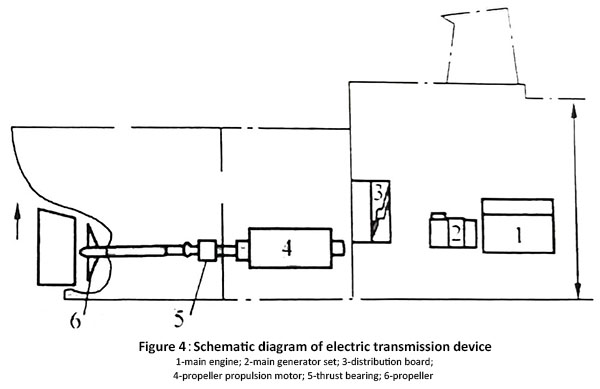
The characteristics of electric transmission devices are:
The speed of the main engine is not limited by the propeller speed, and can use high-speed or medium speed diesel engines, which can operate at a constant speed without changing the steering. By changing the current direction of the propulsion motor, the forward and reverse rotation of the propeller can be achieved. Therefore, the main engine can be operated by an irreversible diesel engine, which is simple and flexible. When suspended, the power generated by the main engine is available for other uses.
Due to its advantages such as good maneuverability and convenient arrangement, this transmission device is used on certain engineering and special vessels, such as tugboats, ferries, dredgers, cable laying ships, and icebreakers.
4. Z-type transmission
Figure 1-6 is the schematic diagram of the Z-type transmission device. The device is divided into a power transmission section and a rotating section of the propeller around the vertical axis. Power transmission part: The power emitted by diesel engine 1 is transmitted through elastic coupling 2, universal joint transmission shaft 3, upper bevel gear 4, vertical transmission shaft 6, lower bevel gear 9, propeller 12, etc., in order to drive the ship's navigation.
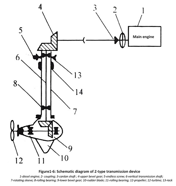
The rotating part of the propeller; Driven by an electric motor, the worm gear 5 is driven through the worm gear 13 to rotate the rotating sleeve 7 in a plane within the rotation range of the bracket 14, in order to control the turning of the ship. Rudder blade 10 plays a role in assisting in controlling the turning of the ship.
The characteristics of this transmission device are: the propeller can rotate 360 degrees around the vertical axis, emergency stop rapid turning, fast forward and backward, lateral movement, and micro speed navigation.
Due to the complex power transmission process of the device, the transmission efficiency is low. Due to its advantages such as good maneuverability, this propulsion device is most suitable for working vessels in ports and small transport vessels navigating narrow waterways.
5. Controllable pitch propeller transmission
The structural feature of this device is that the propeller blades are separated from the propeller hub, and the pitch adjustment mechanism can rotate the propeller blades to change the pitch, thereby changing the rotation of the propeller blades to change the pitch, thereby changing the size of the propeller thrust to adapt to the load of the propeller and the ship. When the pitch of the propeller is adjusted to a negative value, the thrust is negative and the ship will start to retreat. (specific composition and structure are shown in Figures 1-7 and 1-8).
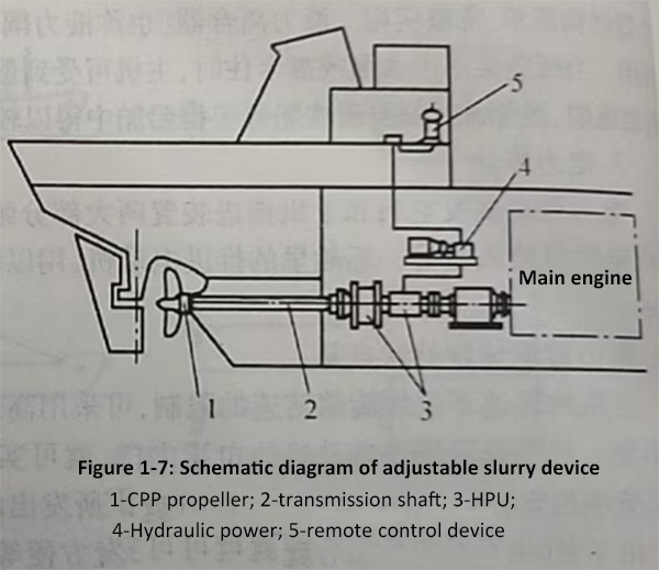
The setting of the controllable pitch propeller device is to rotate the blades at a certain angle simultaneously, so that the propeller can be in a state such as "forward" (positive pitch angle, thrust backward), "stop" (pitch angle is zero, thrust is zero), or "reverse" (negative pitch angle, thrust forward) according to the command, in order to achieve the purpose of maneuvering the ship.
According to the power form of rotating propeller blades, the rotation methods of adjustable propellers can be divided into manual mechanical hydraulic and electric.
Figure 1-8 is a schematic diagram of a hydraulic operated adjustable propeller device. When lever 7 is pushed to the left, control valve 9 moves to the left from the center position, and inlet pipe 11 is connected to the oil circuit on the right. Pressure oil enters the left side of hydraulic piston 12, pushing the piston forward and passing through the hollow rod 3, clamp 4, and pin 5 on the blade root to rotate the blade. When the blade rotates to the desired angle, stop lever 7, track lever 8 to pull control valve 9 back to its original middle position, and cut off the power, and the blade stops rotating. The pressure oil in the inlet and outlet control valve 9 is provided by a dedicated electric pump.
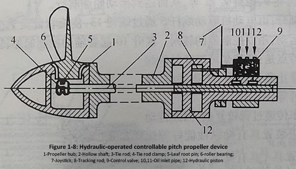
The controllable pitch propeller device has the following characteristics:
(1) The forward and backward movement of a ship does not require changing the direction of the main engine and propeller, but can be achieved by rotating the propeller blades. This only requires the use of a single revolution diesel engine, making the device simple and lightweight.
(2) When a ship navigates under partial load, by adjusting the pitch of the propeller, the main engine and propeller can achieve good coordination, and the main engine operates at fuel consumption, improving economy and increasing endurance.
(3) The ship has good maneuverability and maneuverability.
(4) The complex manufacturing and installation of the blade and shaft system of the adjustable propeller is difficult, and the initial investment is high.
(5) The blade size is relatively large, and its maximum efficiency is 1% -3% lower than that of fixed pitch propellers with the same parameters.
Based on the above analysis, it can be concluded that the adjustable distance is suitable for ships under various navigation conditions. And ships with high maneuverability requirements or suspected low-speed navigation. Such as rescue boats, salvage boats, dredging boats, fishing boats, and icebreakers (Figure 1-5 (g)).
