The main components of marine rudder device
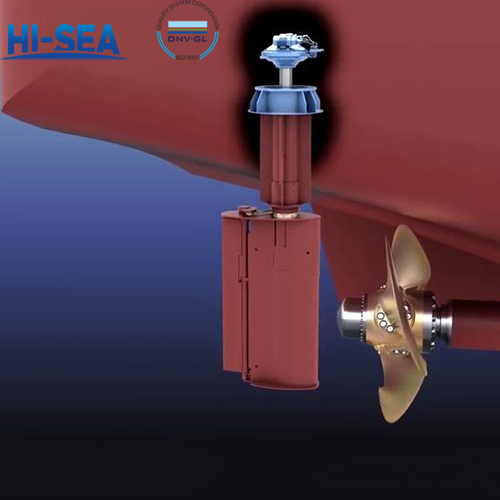
The marine rudder device mainly consists of the following key components, each of which plays an important role in the operation and function of the rudder: rudder blade, rudder stock, rudder bearing, rudder column, rudder hanging arm, rudder pin, rudder knob, rudder support, rudder handle, jump stop ring, rudder angle limiter, etc.
Overview
1. Rudder blade
Rudder blades are components that generate rudder pressure. Most modern seagoing vessels use streamlined profile rudder blades with welded structures, which are mainly composed of rudder blade side plates, vertical partitions, horizontal partitions, rudder stems, and rudder pins.
2. Rudder stock
The rudder stock is the pivot of the rudder, and the upper part of the rudder stock is commonly connected to the rudder stock through methods such as keyed, tight fitting, or keyless connection, and is supported at the rudder bearing. The lower part of the rudder stock is commonly connected to the rudder blades using methods such as horizontal flanges, tapered keyed or non keyed connections. A lower curved rudder stock has an end structure that forms a horizontal or vertical flange, while a lower vertical rudder stock has an end structure that forms a horizontal flange or cone.
3. Rudder bearing
Rudder bearing is a bearing device fixed on the hull to support the rudder stock. Rudder bearings can be divided into supporting rudder bearings and supporting thrust rudder bearings according to their stress state; According to their installation positions, they can be divided into upper rudder bearings, middle rudder bearings, and lower rudder bearings; According to their tightness, rudder bearings can be divided into watertight and non watertight. The friction pair of rudder bearings can use sliding bearings or rolling bearings.
The upper rudder bearing is usually a supporting thrust rudder bearing, which not only bears radial loads caused by hydrodynamic forces acting on the rudder, but also axial forces caused by the gravity of the rudder stock and rudder blades. When the upper rudder bearing of certain ships has become a component of a certain plunger type or rotary vane type servo, it is not necessary to install a separate upper rudder bearing.
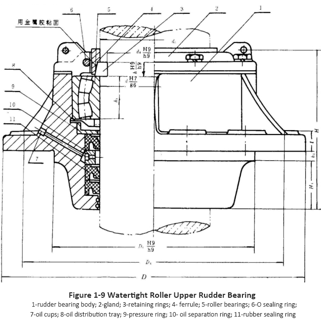
Figure 1-9 shows the water tight roller upper rudder bearing, which uses double row radial spherical roller bearings.
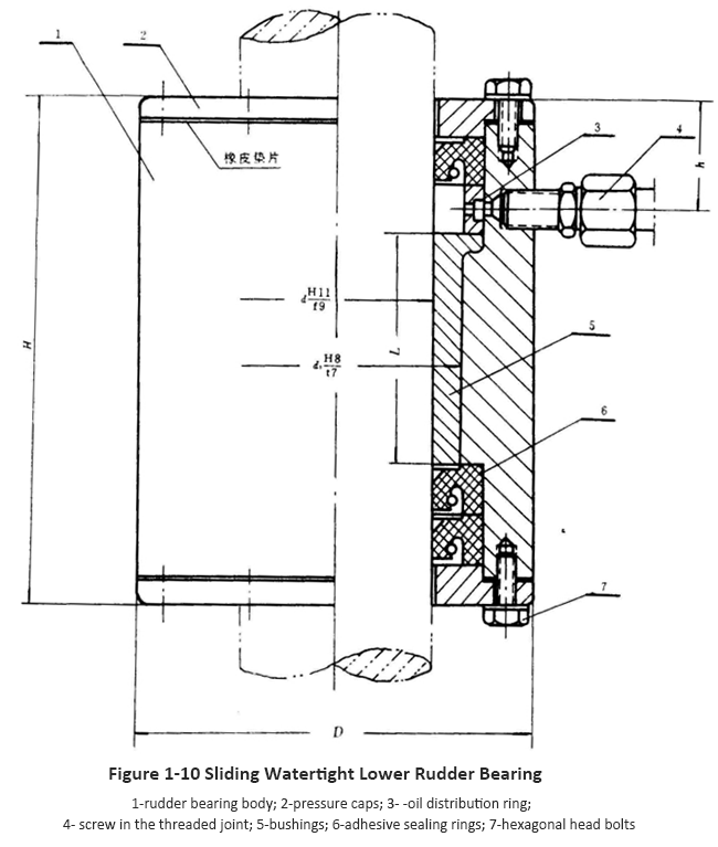
The middle and lower rudder bearings are both supporting rudder bearings and can only withstand radial loads. Middle rudder bearings are rarely used, and sometimes rudders with two or more rudder pins do not have lower rudder bearings. The watertight lower rudder bearing shown in Figure 1-10 is made of cast steel and fixed in constant contact with the hull structure. The lower end of the rudder bearing is equipped with a sealing ring and a pressure cap, which is suitable for shallow water areas with a lot of cement sand.
4. Connection between rudder stock and rudder blade
The commonly used connection method for the rudder stock and rudder blade is flange connection and cone connection.
5. Rudder column
The wheel column is a cylindrical component of the ship's hull that supports unbalanced energy. Sometimes its cross-sectional shape is designed to match the camel leaf profile, forming a combined streamlined agent surface to improve the efficiency of the rudder.
6. Rudder horn
The rudder horn is an arm shaped component attached to the stern of the ship to support a semi suspended rudder. It is generally designed with a streamlined profile that matches the rudder blades.
7. Rudder pin and rudder knob
When the rudder blade is connected to the rudder pillar or rudder arm by a rudder pin, several perforated protrusions are correspondingly set on the rudder blade, rudder pillar or rudder arm, which are called rudder knobs. Insert the rudder pin into the rudder knob hole, ensuring a reliable connection between the rudder blade and the rudder pillar or rudder arm. The connection method between the semi suspended rudder and the rudder arm is shown.
8. Rudder support (rudder heel)
Nengtuo (Hualuo) refers to the protruding part located at the bottom of the tail column, also known as the bottom support seat, used to install the lower Nengpin or rudder shaft.
9. Tiller
A tiller is usually a component installed on the head of a rudder stock to rotate it. Its shape varies depending on the steering device and can sometimes be used as a component of the servo.
10. Stop Ring
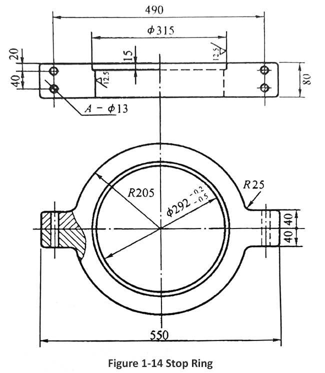
During navigation, the rudder blades may experience vertical movement due to wave impact and other factors. To prevent the rudder from being lifted, appropriate stop ring should be installed to prevent the rudder from being lifted up. A dedicated jump stop ring can be installed between the lower end face of the lower rudder bearing and the upper end face of the rudder blade for hanging the rudder. Its structure is shown in Figure 1-14. The jump stop ring or retaining ring sleeve is made into a symmetrical shape, connected with bolts to form a complete circle, and is left loose on the rudder stock.
11. Rudder angle limiter
A rudder angle limiter is a limiting device used to prevent the rudder blade angle from exceeding the allowable limit angle. Usually installed on the deck (or platform) where the servo and steering machinery are located, and on the rudder blades. The steering device for power steering should not only be equipped with limit switches or similar devices to limit the maximum steering angle, but also with mechanical braking devices to limit the steering angle in the event of limit switch failure. This angle should be 1.5 ° to 2.0 ° larger than the maximum operating angle.
Hydraulic servos usually have a mechanical braking device inside the hydraulic cylinder, so there is no need to install a separate mechanical braking device. Electric servos often have mechanical braking devices installed on both sides of the rudder fan.
The rudder angle mechanical braking device is installed on both sides of the rudder handle, and the braking device should have a sturdy structure and be firmly connected to the hull structure.
For more marine rudder system information, kindly please click here.

