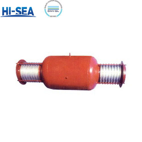
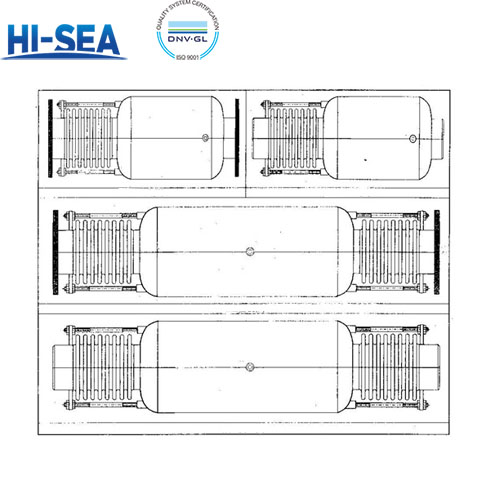
The Bypass Type Straight Pipe Pressure Balanced Expansion Joint
Bypass straight pipe pressure balance compensator is a device used to compensate the axial displacement caused by temperature difference, settlement, vibration and other factors in pipeline system. It has the advantages of small volume, low cost, good guidance, good stability, etc. It can effectively absorb the axial displacement of the pipeline and balance the internal pressure thrust of the bellows.
Overview
Advantages
(1) Absorption of internal pressure thrust: the by-pass straight pipe pressure balance compensator has the ability to absorb internal pressure thrust, and can self-balance the internal pressure thrust, reducing the need for fixed supports.
(2) Superior self-balancing: compared with other types of compensators, the by-pass straight pipe pressure balance compensator has superior self-balancing, which can better cope with the pressure changes inside the pipeline.
(3) Small stiffness and good orientation: the compensator has small stiffness and good orientation, which can better adapt to the displacement changes of the pipeline.
(4) Small external dimensions: the external dimensions of the by-pass straight pipe pressure balance compensator are small and economical, suitable for use in occasions with limited space.
(5) Installation without directional requirements: the installation of the compensator has no directional requirements, installation is more simple.
Structural characteristics
Small volume and low cost: due to its simple design, less material is used, so the cost is low.
Good orientation and stability: the design of the bellows makes it have good orientation and stability when absorbing displacement.
Nominal Diameter DN mm | Bellows n | Axial compensator X0 mm | Axial stiffness KX0 N/mm | Radiak shape Maximum size B mm | Product Length L mm | Product Type | |
Connection form | |||||||
Take over J | Flange F | ||||||
Design pressurePD=0.6MPa (16kgf/cm2) Fatigue life [N]=200 Design temperature t=20℃ | |||||||
100 | 16 | 49 | 810 | 230 | 1100 | 1110 | PYP |
32 | 98 | 405 | 1549 | 1560 | |||
125 | 16 | 48 | 964 | 280 | 1159 | 1170 | |
32 | 96 | 482 | 1657 | 1667 | |||
150 | 16 | 46 | 1129 | 325 | 1198 | 1210 | |
32 | 92 | 565 | 1646 | 1656 | |||
200 | 16 | 78 | 1309 | 426 | 1554 | 1578 | |
32 | 156 | 655 | 2178 | 2200 | |||
250 | 16 | 75 | 1602 | 529 | 1648 | 1672 | |
32 | 150 | 801 | 2265 | 2290 | |||
300 | 16 | 98 | 1347 | 630 | 1887 | 1910 | |
32 | 196 | 674 | 2612 | 2636 | |||
350 | 16 | 95 | 1539 | 670 | 1982 | 2010 | |
32 | 190 | 770 | 2705 | 2730 | |||
400 | 16 | 93 | 1726 | 720 | 2100 | 2124 | |
32 | 186 | 863 | 2827 | 2852 | |||
450 | 16 | 91 | 1921 | 820 | 2146 | 2170 | |
32 | 182 | 961 | 2867 | 2890 | |||
500 | 16 | 90 | 2112 | 920 | 2241 | 2265 | |
32 | 180 | 1056 | 2962 | 2986 | |||
600 | 16 | 132 | 2390 | 1120 | 2991 | 3015 | |
32 | 264 | 1195 | 4142 | 4166 | |||
700 | 12 | 130 | 3471 | 1220 | 3255 | 3280 | |
24 | 260 | 1736 | 4480 | 4504 | |||
800 | 12 | 128 | 3821 | 1320 | 3434 | 3458 | |
24 | 256 | 1911 | 4658 | 4682 | |||
900 | 12 | 126 | 4188 | 1520 | 3643 | 3667 | |
24 | 252 | 2094 | 4896 | 4920 | |||
1000 | 12 | 144 | 4712 | 1620 | 3842 | 3866 | |
24 | 288 | 2365 | 5104 | 5128 | |||
1100 | 12 | 141 | 5112 | 1720 | 4000 | 4024 | |
24 | 282 | 2556 | 5261 | 5285 | |||
1200 | 12 | 139 | 5517 | 1920 | 4160 | 4184 | |
24 | 278 | 2769 | 5419 | 5444 | |||

