
Terminology, definitions, symbols, and units for marine propellers
Marine propellers are the core components of a ship's propulsion system.
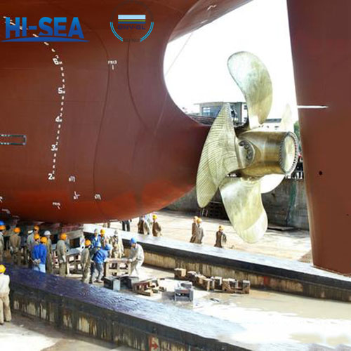
A propeller consisting of a hub and several radially fixed blades, commonly known as a wheel blade.
The propeller is installed below the waterline at the stern of the ship, and is powered by the main engine to rotate, pushing water towards the back of the ship and using the reactive force of the water to propel the ship forward.
The propeller has a simple structure, light weight, high efficiency, and is protected below the waterline.
The terms and definitions specified in GB/7727 and the following are applicable to this standard (GB/T 12916-2010).
Overview
The terms and definitions specified in GB/7727 and the following are applicable to this standard (GB/T 12916-2010). The symbols and units of the main terms are shown in Table 1.
1. Radius of propeller: The radius of the blade tip trajectory circle when the propeller rotates.
2. Radius of blade section: The radius of the intersection between the propeller blade and the coaxial cylindrical surface on the propeller.
3. Width of propeller blade section: The unfolded width of the cross-section between the propeller blade and the coaxial cylindrical surface.
4. Propeller local pitch: The axial height difference between two points on the pressure surface of the propeller blade at different positions with a radial angle of β at the same radius.
5. Pitch of blade section: The arithmetic mean of the local pitch values at the intersection of the propeller blade and the coaxial cylindrical surface.
6. Mean pitch of blade: When the propeller blades are of equal pitch, it is the arithmetic mean of the pitch values of each section; When the propeller blades have variable pitch, the pitch value of the 0.7R section is generally taken.
7. Mean pitch of propeller: the arithmetic mean of the pitch of each blade.
8. Area ratio of propeller: The ratio of the unfolded area of each blade of the propeller to the projected area.
9. Angle of blades: the angle between the reference lines of adjacent blade surfaces.
10. Thickness of blade section: The thickness at various points on the cross-section of a propeller blade.
11. Adding weight of propeller still balance: When performing static balance on a propeller, the minimum weight of the weight that can be hung at the maximum thickness of each blade tip to allow it to rotate downward.
12. Mass of propeller: The sum of the mass of propeller blades, hub mass, and fillet packing mass.
13. Speed of propeller: The rotational speed at which the propeller operates at rated power.
14. Propeller surface area discontinuity: The surface area of the area where the propeller defect is displayed.
15. Height margin of propeller local pitch: The difference in axial height of the local pitch of a propeller at the same radius.
16. Number of propeller blades: The total number of blades on a single propeller.
17. Suction side: The side where the propeller blades absorb water under negative pressure when the ship is moving forward, which is the suction side.
18. Pressure side: The side where the propeller blades push water when the ship is moving forward is the pressure side.
19. V-plane: The reference plane perpendicular to the propeller shaft, which is the V-plane.
20. Non concentrated discontinuity: Defects such as air holes and slag inclusions with no more than 4 points per square centimeter on the surface of the propeller, which are classified as non concentrated defects.
Table 1 Terminology, Symbols, and Units for marine propeller

For more marine propeller information, kindly please click here.