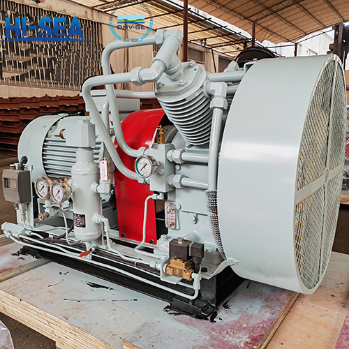
Structure of marine piston air compressor
Marine piston air compressor is a commonly used compressor on ships, used to compress air to meet the needs of various ship equipment.
Main structure: cylinder, piston, air valve, safety valve, unloading mechanism, gas-liquid separator, lubrication, cooling.
Overview
The structure of a piston air compressor is similar to that of a piston refrigeration compressor and a reciprocating pump, but due to different working media, there are significant differences in structure. The drawing shows the structure of CZ60/30 marine air compressor, which is a vertical, water-cooled, two-stage air compressor. The air compressor has a displacement of 60m3/h and a speed of 750r/min. The rated exhaust pressure of the low-pressure stage is 0.64MPa, and the rated exhaust pressure of the high-pressure stage is 3MPa.
For more marine air compressor information, please click here.
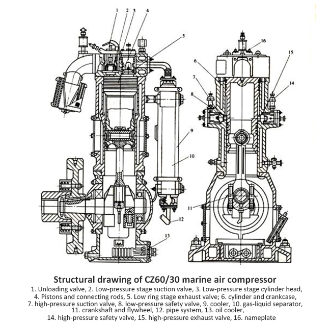
The electric motor drives the crankshaft to rotate through an elastic coupling, and then drives piston 4 to move up and down in cylinder 6 through connecting rods and piston pins. The air is sucked into the low-pressure cylinder through the filter and low-pressure suction valve; After being compressed by the piston, it is discharged from the low-pressure exhaust valve located at the cylinder head. The air discharged from the low-pressure stage is cooled by the intercooler and then sucked into the high-pressure stage cylinder for secondary compression through the high-pressure stage suction valve. After compression, it is discharged from the high-pressure exhaust valve, and the discharged air is then cooled and gas-liquid separated before being discharged into the air cylinder. Throughout the compression process, the pressure of the air increases step by step, and the temperature also increases step by step.
1. Cylinder and piston
Marine piston air compressors often use differential cylinders and pistons to reduce machine size. As shown in the figure, both the cylinder and the aluminum alloy cast piston are divided into two sections with a diameter of upper and lower. The low-pressure stage workspace is composed of piston 4, cylinder 6, and cylinder head 3; The high-pressure working space is an annular chamber composed of piston 4 and cylinder 6. When the piston moves from top dead center to bottom dead center, the low-pressure stage of the air compressor is in the suction process and the high-pressure stage is in the exhaust process. Conversely, when the piston moves from bottom dead center to top dead center, the low-pressure stage of the air compressor is in the exhaust process and the high-pressure stage is in the suction process. Therefore, the sealing performance of the piston has a significant impact on the operation of the compressor. Generally, the upper section of the piston has 6 piston rings, the lower section has 6 piston rings, and 1 oil scraper ring.
The thickness of the gasket between the cylinder and the cylinder head will affect the clearance volume of the low-pressure stage. The thicker the gasket, the larger the clearance volume. Generally, the clearance between the piston and the cylinder head should be maintained at 0.5-1.0mm when the piston is at the top dead center. The thickness of the gasket between cylinder 6 and the crankcase has an impact on the clearance volume of both the low-pressure and high-pressure stages. However, it should be noted that when adjusting the thickness of the gasket between cylinder 6 and the crankcase, the effect on the clearance volume of the low-pressure and high-pressure stages is completely opposite. For example, when the gasket thickness increases, the clearance volume of the low-pressure stage increases, while the clearance volume of the high-pressure stage decreases. On the contrary, when the thickness of the gasket decreases, the clearance volume of the low-pressure stage decreases, while the clearance volume of the high-pressure stage increases.
2. Air valve
The suction valve 2 and exhaust valve 5 of the low-pressure stage are vertically installed on the cylinder head 3; The suction valve 7 and exhaust valve 15 of the high-pressure stage are perpendicular to the cylinder and installed in the valve chamber in the middle of the cylinder.
The lift of the air valve disc has a significant impact on the economic life of the compressor. Reasonably increasing the lift can reduce the airflow velocity in the valve gap and reduce the resistance loss of the valve; But as the lift increases, the impact speed of the valve disc on the lift limiter and valve seat will also increase, and the deformation amount and deformation speed of the valve spring will also increase. This will lead to a decrease in the service life of the air valve, and will also increase the lag of the air valve closing. In severe cases, it may even cause the compressor to not work properly. Therefore, the lift of the air valve is selected based on experience and experimental data during design, and is limited by a lift limiter. The lift specified in the manual should not be changed arbitrarily. The lift of the air valve is mostly around 2-4mm, while those with high rotational speed and high working pressure have a smaller lift. Due to different pressures, the volume flow rate of air passing through the low-pressure stage is greater than that of the high-pressure stage, so the lift of the air valve in the low-pressure stage is usually greater than that in the high-pressure stage. In this example, the valve disc lift of the low-pressure stage valve is 3mm, and the valve disc lift of the high-pressure stage valve is 2.1mm.
When repairing air valves, attention should be paid to:
(1) The suction and exhaust valve plates and springs cannot be replaced incorrectly.
(2) Check if the lift of the valve plate meets the requirements and if there is any jamming phenomenon on the valve plate.
(3) After maintenance and assembly, the gas valve should be tested for leakage with kerosene, and dripping leakage is allowed. A leakage rate of less than 20 drops per minute is considered qualified.
(4) Before installing the air valve, the copper gasket should be annealed.
The requirements for air valves and reciprocating pump valves have similarities, such as simple processing technology and convenient maintenance in structure, tight closure, low resistance, and timely opening and closing in performance. However, due to the low gas density, although the airflow velocity passing through the valve is high, the pressure drop is not too large, and there may be a problem of liquid vaporization during pump suction. Therefore, the speed of the air compressor is much higher than that of reciprocating pumps (micro and small air compressors can reach 1000-2500r/min), and it is impossible to require the valve to work silently. Only the impact speed between the valve plate, valve seat, and lift limiter should not be too large to ensure a longer working life (at least 4000h or above). In addition, it is also required to minimize the clearance volume formed by the air valve channel as much as possible.
In addition, the strength of the air valve spring also has a significant impact on the operation of the air valve. If it is too strong, the resistance of the valve will increase; If it is too weak, the closing will be more delayed. Seating is exacerbated by the impact of reverse airflow, which will reduce the service life of the valve; Both will increase the loss of exhaust volume and power.
There are many forms of air valves, including ring valves, mesh valves, disc valves, bar valves, and tongue spring valves. The most commonly used marine air compressor is the annular valve. Illustrate the single ring (high-pressure stage) and double ring (low-pressure stage) annular valves used in this example. The circular valve has a simple structure, good processability, low price, convenient maintenance, and is easy to open and unload the suction valve. The disadvantage is that the guiding friction of the valve plate movement is relatively high, and in order to maintain sufficient rigidity, the valve plate is slightly thicker and has a larger mass, which is not suitable for too high speeds (n ≤ 1500r/min). The use of multi ring valve plates can increase the flow area and adapt to larger volumetric flow rates. However, each ring valve plate may not be synchronized, which can have adverse effects on work.
Low speed and high displacement air compressors can use mesh valves, while disc valves are mostly used in the high-pressure stage of small air compressors with low speeds. High speed air compressors can use bar valves and tongue spring valves.
3. Safety valve
The differential air compressor's low-pressure and high-pressure stages are equipped with safety valves. In this example, low-pressure safety valve 10 and high-pressure safety valve 22 are installed at the suction and discharge valve chambers of the high-pressure stage, respectively. The opening pressure of a general low-pressure safety valve is 15% higher than the rated discharge pressure, and that of a high-pressure safety valve is 10% higher than the rated discharge pressure. The safety valve is an automatic safety protection device for the air compressor. When the pressure exceeds the set value, the safety valve automatically opens to release gas. When the pressure drops to a certain value, the safety valve closes on its own. The safety valve should have stable operation, reliable operation, and good airtightness when closed, and the air release when opened should be equal to or slightly greater than the compressor's exhaust volume.
4. Unloading mechanism
When starting the air compressor, to reduce the starting current and avoid excessive force on machine components causing damage, it must be unloaded during the starting period. The commonly used unloading methods include opening the suction valve and exhaust bypass. In this example, the manual opening of the suction valve is used. Before starting the air compressor, manually lift the eccentric handle to press down on piston 5, open the low-pressure stage suction valve, and keep it open during startup. Until the compressor reaches normal speed, manually lower the eccentric handle to turn the low-pressure suction valve into a normal state, and the air compressor begins the normal compression process at the same time.
5. Gas-liquid separator
The exhaust of each level of the cylinder will carry small oil droplets, and the partial pressure of water vapour in the exhaust is also high, which will precipitate condensation after cooling. After the first stage of cooling, the oil and water can be partially separated and accumulate in the air pipeline between the interstage cooler and the inlet of the high-pressure cylinder. There is usually a relief valve to release them. Install a gas-liquid separator after the cooler to improve the quality of compressed air filled into the gas cylinder. There are three types of gas-liquid separators based on their working principles: inertial, filtering, and adsorption. The diagram shows the inertia equation. Its working principle is to use the different densities of liquid droplets and gases to change the direction of airflow multiple times, causing the droplets to collide and adsorb on the wall of core 7, gather and flow to the lower space of shell 6. To prevent the airflow from returning to the air compressor during parking, the steel ball valve 4 in the gas-liquid separator serves as an air check valve; The relief valve 8 at the bottom of the separator is used to discharge the separated oil and water.
6. Lubrication
There are two lubrication methods for air compressors: splash lubrication and pressure lubrication. Small marine air compressors often use splash lubrication. When the air compressor is running, the oil spoon 18 on the connecting rod's large end bearing cover in Figure 2-4 splashes the lubricating oil in the crankcase. The splashed oil droplets can lubricate the main bearing, connecting rod small end bearing, and the lower working surface of the cylinder. At the same time, a portion of the oil flows along the small hole on the front of the oil spoon and the oil guide hole on the large end of the connecting rod to lubricate the bearing on the large end of the connecting rod. The upper wall of the cylinder is lubricated by 4-6 drops of oil per minute from the oil cup on the low-pressure air suction pipe, or by sucking some oil mist from the crankcase through the connecting pipe. The crankcase door cover is equipped with a dipstick 20 for measuring the oil level, which can be used to add lubricating oil. The oil level in the crankcase should be moderate. If the oil level is too low, it can cause poor lubrication. If the oil level is too high, it can cause excessive splashing, which not only increases power consumption but also makes the lubricating oil prone to deterioration. Moreover, excessive lubricating oil entering the cylinder can affect air quality, causing valve coking and piston ring failure.
7. Cooling
Cooling is crucial for air compressors. There are two cooling methods: water cooling and air cooling. Most marine air compressors are water-cooled and do not come with their own water pumps. The required cooling water comes from the seawater system in the engine room. Ships with a central cooling system can use fresh water circulation cooling.

