Special rudder and its types
In addition to conventional rudders, there are many different forms of special rudders to improve the efficiency of rudders and propellers.
Some ships often use special energy or special control devices to meet their special requirements for maneuverability, such as increasing energy efficiency, improving propulsion efficiency, improving the diameter of the Weixiaozu return circle, and improving the maneuverability of large ships at low speeds.
For example, reaction rudders based on the principle of lift, rectifier cap rudders, flap rudders, and combination rudders, active rudders based on the principle of thrust, rotating guide tube rudders, and fully rotating propulsion devices.
Overview
1. Reaction rudder
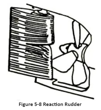
The Reaction Rudder is shown in Figures 5-8. This type of rudder is bounded by the axis of the propeller and twisted at an angle to the left and starboard (for a right-handed propeller) on the leading edge of the rudder blade, making it conform to the direction of the flow discharged from the propeller disk, hence it is also known as an upstream rudder. This type of rudder can reduce the resistance of the rudder and improve propulsion efficiency, but it has no significant effect on improving maneuverability.
2. Active rudder
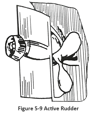
The Active Rudder is shown in Figures 5-9. There is a guide tube installed at the trailing edge of the rudder blade, which houses a small propeller driven by an electric motor installed inside the blade. When turning the rudder, the propeller rotates and releases thrust, and its lateral force can increase the turning moment of the ship. When the ship is at low speed or even when the main engine is parked, the turning moment can also be obtained, thereby improving the maneuverability of the ship. It is mostly used by small boats with high requirements for turning and frequent berthing at the dock (such as patrol boats, pilot boats, ferries, etc.). Due to the fact that the propellers on the rudder can also be used as micro propellers, they are also applied on some scientific research ships.
3. Bulb Rudder
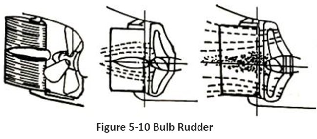
Bulb Rudder, as shown in Figures 5-10. A conical streamlined body, commonly known as a rectifier cap, is installed at the position of the streamlined rudder facing the propeller axis. Its function is to improve the state of the propeller discharge flow, reduce turbulence, thereby increasing the thrust of the propeller and helping to reduce the vibration of the stern.
4. Flap rudder
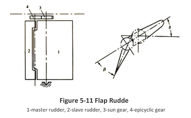
The Flettner Rudder or Flap Rudde is shown in Figures 5-11. This type of rudder is equipped with a large rudder blade called a flap at the trailing edge of the main rudder blade, which is hinged with a pin between the main and auxiliary rudder. Due to its similar hydrodynamic characteristics to the flaps on an aircraft, it is called a flap rudder. Wing rudder refers to a rudder composed of a main rudder blade and flaps. The flaps are connected to the trailing edge of the main rudder blade and can be independently controlled by a separate mechanism. The rotation direction of the flaps can be consistent with the main rudder blade, but the angle is greater than the rudder blade angle. There are also flaps that rotate in the opposite direction to the main rudder blade. Flap rudder can improve rudder efficiency or reduce rudder torque.
5. Kort Nozzle Rudder
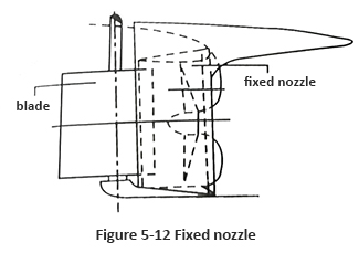
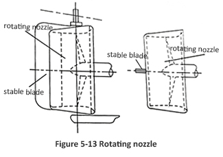
A guide pipe is a short section of duct installed at the surface of a propeller. The propeller is located at the narrowest section inside the guide tube, which can improve the wake state, increase propulsion efficiency, and have good performance in both forward and reverse directions. It can also protect the propeller and prevent ropes from getting entangled with people. There are two forms of guide pipes: fixed guide pipes and rotating guide pipes. The fixed guide pipe (see Figure 5-12) is fixed to the stern frame without moving, and the rudder is set behind the guide pipe. The rotating guide tube (see Figure 5-13) is a device that directly installs the guide tube under the rudder and rotates it by the rudder, replacing the rudder. When the guide pipe deflects, it changes the direction of the discharge flow, resulting in greater lateral thrust and turning moment than conventional rudder lift. But when the ship navigates through inertia, the effect is minimal, and a stabilizing blade can be installed on the longitudinal section at the rear of the guide pipe to compensate.
6. Unit Rudder
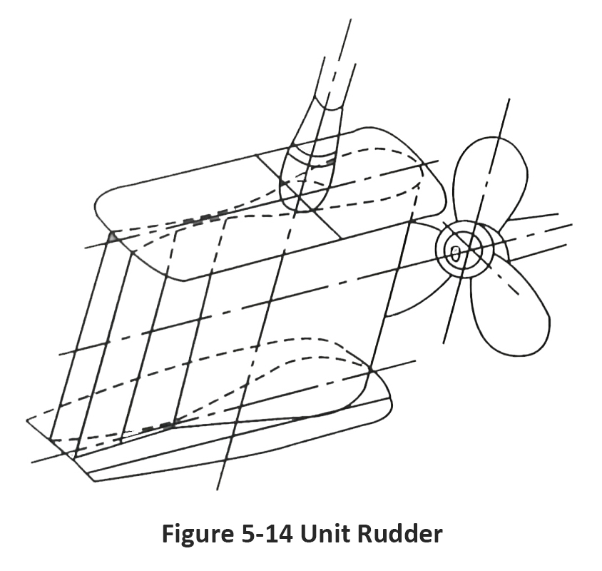
For rudder with a small aspect ratio, the lateral flow along the top and bottom of the rudder blade is relatively large. In order to reduce the flow loss at the upper and lower ends of the rudder blade and further improve the fluid performance of the rudder, a flow control plate is installed at each end of the rudder blade. This type of rudder is also known as Schilling Rudder or I-shaped rudder. It is designed to resemble the shape of a fish tail (called a fish tail rudder) along the edge, with the enlarged part accounting for about 20% of the chord length, and gradually transitioning to the narrow part and thicker tail, increasing the wing arch to a certain extent. Usually, the centerline of the rudder stock is at a chord length of 40% from the guide edge, in order to control more wake. This type of rudder has a lift coefficient of about 1.5 times that of a regular rudder at commonly used rudder angles, and can achieve good rudder performance at low speeds and in shallow water. A rudder type with a small aspect ratio that is particularly suitable for ships in inland rivers, canals, and restricted waterway waters. Its rudder angle can be used within a range of ± 75 °. For small aspect ratio rudder, installing flow restrictors up and down is effective in increasing rudder pressure. As shown in Figures 5-14.
7. Rotating cylinder Rudder
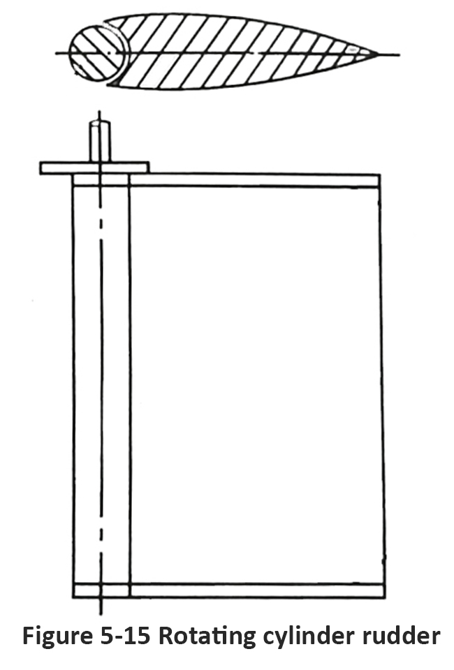
A column rudder is installed at the leading edge of the rudder - a column that can rotate in both directions and maintain a wing shaped profile with the rudder body as a whole, as shown in Figures 5-15. If the steering column does not turn, it is a regular rudder. Rotary column rudder, also known as rotary column rudder. A rudder with a vertical cylinder that rotates actively at the leading edge of the rudder blade. According to the Magnus effect principle, when a cylinder rotates in water, it will generate vertical inflow and lift in the direction of the rotation axis. The rotary column rudder is a combination of a regular streamlined rudder and a rotary column. When operating the left rudder, the steering column must rotate clockwise, otherwise the steering column must rotate counterclockwise. In this way, the suction surface of the rudder accelerates the water flow, while the pressure surface slows down the water flow, thereby increasing circulation and lift, and delaying lift failure. The loss of lift rudder angle is about 60 ° or above, and the maximum rudder angle can reach 90 °. The rotary column rudder is an efficient active control device for improving the maneuverability of ships, characterized by high turning torque, low power consumption, high hydrodynamic efficiency, and simple construction. Suitable for low-speed ships, but can also have special effects when used on high-speed ships: at high speeds, only the rudder behind is used without turning the steering column; Start the turning column to improve the maneuverability of the ship. In addition to being used together with a regular rudder, the steering column itself can also be used separately for longitudinal installation at low speeds or when approaching or leaving the dock. If the steering column is installed in front of the oar, it can be used for reversing the ship, and the effect is better than that of a general reversing rudder.
For more marine rudder system information, kindly please click here.
For more marine rudder system components, kindly please click here.

