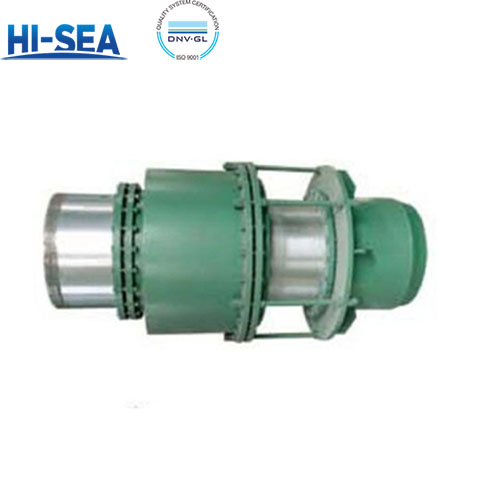
Sleeve Compensator
Sleeve compensator is a compensation device for hot fluid pipeline, mainly used to absorb the axial thermal expansion displacement caused by temperature change after pipeline laying, to maintain the sealing and integrity of the pipeline system, and at the same time cushion the impact of pressure fluctuation on the pipeline, reduce pipeline stress, and Extend the service life of the pipeline.
Overview
Structural characteristics
Sleeve compensator is mainly composed of sleeve (core tube), shell and sealing material.
Through the sliding sleeve to the outer sleeve of the sliding movement, to achieve the compensation of thermal expansion.
It is characterized by small volume and large compensation volume, and is suitable for hot water, steam and grease media.
Application
Suitable for medium engineering pressure ≤ 2.5MPa, medium temperature -40 ℃ ~ 600 ℃.
There is no requirement for chlorine ion content, especially suitable for the medium or the surrounding environment chloride ion exceeds the standard system.
Directly buried sleeve compensator can be buried directly in the ground, the installation can not set up maintenance wells, low construction cost.
The following matters need to be noted when installing:
(1) Check the packing and casing status: before installation, check whether the packing is filled, if not, it should be added and pressed. If the casing is found to be corroded or not stretching, it should be disassembled and cleaned before assembling, and the packing should be replaced if it has been hardened.
(2) Pre-stretching and checking the gap: the casing should be withdrawn first during installation, and the withdrawal length should be pre-stretched according to the designed expansion figure, and the effective size of the gap should be checked in detail after stretching to ensure that the compensator can work normally and avoid failure.
(3) Installation direction: the installation direction of the sleeve compensator should be consistent with the flow direction of the medium in the pipeline. Manufacturers will usually be in the sleeve compensator shell labeled with an arrow, indicating the direction of flow of the medium, the installation should ensure that the direction of the arrow and the direction of flow of the medium is consistent.
(4) Setting guide bracket: sleeve compensator should be installed near the fixed bracket, the casing shell end toward the fixed bracket of the pipeline, the telescopic casing end is connected with the pipe that produces thermal expansion and contraction. In order to ensure that the pipe is concentric with the compensator, 1-2 guide brackets are required in the direction of the expansion and contraction end of the compensator.
(5) Protect the sliding surface: In the process of installation and use, attention should be paid to the protection of the sliding surface of the sleeve compensator, and it is strictly prohibited to bruise or corrode, so as to ensure its sliding performance and service life.
(6)Check the specification and model: before installation, the specification and model of sleeve compensator should be carefully checked whether it is the same as the ordered one to make sure it is suitable for the current pipeline system.
(7) Welding and pressure test: the pipe sections welded to the ends of the compensator must be beveled, and after welding, a hydraulic test should be carried out according to the acceptance specification, and the pressure should be 1.5 times of the working pressure. Test pressure, such as sealing device leakage, should be uniformly tightened bolts, tighten until no leakage.
(8) Protection of expansion pipe components: expansion pipe components should be strengthened in the installation process to protect the metal surface shall not be scratched with hardware. In the compensator and pipe butt welding shall not be in the expansion pipe sliding parts of the arc, lap wire.
(9) insulation protection: in the pipe insulation protection should be done before the compensator to do simple protection, shall not be exposed, in order to prevent man-made touching, smashing, scratching, insulation materials shall not hinder the normal work of the sliding parts.
(10) installation in the cold season: in the cold season installation welding, should be welded parts of the pipe end preheating, in order to prevent cold brittleness after welding.
Unidirectional compensation technology parameter table | |||||
Nominal Diameter DN mm | Maximum outer diameter D mm | Compensation amount mm | Maximum assembly length mm | Weight Kg | |
Take over | Flange Type | ||||
40 | 144 | 200 | 600 | 6.5 | 8.3 |
50 | 160 | 200 | 600 | 10 | 15 |
65 | 180 | 200 | 600 | 16 | 21 |
80 | 195 | 200 | 650 | 17 | 24 |
100 | 215 | 200 | 700 | 25 | 33 |
125 | 245 | 200 | 700 | 32 | 41 |
150 | 280 | 250 | 800 | 45 | 56 |
200 | 335 | 250 | 800 | 70 | 87 |
250 | 405 | 250 | 800 | 90 | 114 |
300 | 460 | 250 | 800 | 120 | 148 |
350 | 520 | 250 | 850 | 140 | 172 |
400 | 580 | 300 | 1000 | 185 | 225 |
450 | 640 | 300 | 1000 | 205 | 251 |
500 | 705 | 300 | 1000 | 245 | 309 |
600 | 840 | 300 | 1000 | 305 | 401 |
700 | 930 | 300 | 1050 | 370 | 480 |
800 | 1030 | 300 | 1050 | 405 | 533 |
900 | 1130 | 300 | 1050 | 490 | 642 |
1000 | 1230 | 300 | 1050 | 515 | 681 |

