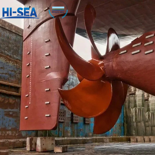
Installation of marine rudder system
Due to the rudder's different structural types, the rudder system's installation method is also different. Taking the ordinary three-fulcrum rudder as an example, the installation process of the rudder system will be introduced below.
Overview
(1) Positioning of upper rudder bearing seat
When pulling the rudder line, the upper rudder seat should be roughly placed in place first, and the rudder line should pass through it. After waiting for the position of the rudder line to be determined, use internal calipers to measure the distance between the upper rudder bearing hole wall and the rudder line, and adjust the position of the seat. Then use a ruler 4 and an angle ruler 3 or a spirit level to check the non perpendicularity between the upper plane and the rudder line, as shown in Figure 2-21. Use a small wedge to adjust the upper rudder seat so that its upper plane is perpendicular to the rudder line. The inspection should be conducted in two perpendicular directions (usually the front and back of the ship, left and right). If the ship is on an inclined shipway, a prefabricated pad iron with the same inclination as the shipway needs to be placed between the level and ruler to check the verticality in the front and back directions (no diagonal pad is required for left and right direction inspection). After adjusting the verticality, recheck the front, rear, left, and right positions of the upper rudder seat. After both requirements are met, measure the distance from the centerline of the shaft system to the upper plane of the upper rudder bearing. If the distance value is greater than the specified value, it should be cut from the lower part of the upper rudder bearing seat. After considering the machining allowance of the upper plane (if the upper plane needs to be machined), adjust the height of the needle plate to the height to be cut, based on the rudder plate, and draw a height line at the lower part of the rudder seat. Use gas cutting to cut on site according to the line. Then, align the upper rudder system seat that has been cut to the correct height (left and right front and rear positions, as well as the verticality of the upper plane with the rudder line) by spot welding and fixing it. After re checking the position, weld the upper rudder bearing firmly on the steering gear deck. After the welding seam cools down, draw the machining circle and inspection circle of the inner hole of the rudder seat according to the rudder line.

(2) Introduction to Rudder Bearing Boring and "Non Boring" Process
The boring method for machining rudder bearing holes is similar to that for machining stern tube holes. This article introduces a "non boring" process, which has certain significance for the installation of rudder systems in batch production of small and medium-sized ships.
The "non boring" process is to pre process the rudder bearing holes in the workshop according to the finished product size, and then weld the rudder bearing seat in the specified position according to the rudder line. The method is to measure the distance between the rudder line and the inner circle of the rudder bearing hole before and after welding, and control welding deformation to make the rudder bearing hole coaxial with the rudder line. For the sake of speed and convenience, a false axis is generally used instead of a steel wire rudder line.
After the machining or positioning of the rudder bearing hole, press the copper sleeve of each gear bearing, and use a sample made of long wooden strips to take the accurate size of the upper plane of the upper rudder bearing seat that can indicate the end face, for use in determining the axial position of the upper rudder shaft ring groove between wheeled locomotives.
(3) Assembly of upper rudder stock and rudder blade
The purpose of assembling the upper rudder stock and rudder blade in the workshop is to calibrate the different axial degrees between the axis of the upper rudder stock and the axis of the rudder blade pin, process the connection plane using the brushing method, tighten the matching bolt holes, and perform key and keyway matching to fix the calibrated position
Calibration work is generally carried out on a tablet. If the rudder stock and rudder blade are longer, the wire drawing method can also be used. Before calibration, the flange end face connecting the upper rudder stock and rudder blade needs to be pre polished with a flat plate, requiring 1-2 color points every 25mm x 25mm. Place the upper rudder stock and rudder blade on the platform and secure them with temporary fixing bolts. First, align the axis of the upper rudder stock parallel to the platform plane, use a compass to determine the height of the rudder stock axis, and then use a compass to determine the height of the rudder blade pin axis, with a difference of 0.5mm. Then turn the rudder stock and rudder blades together around the axis of the rudder stock by 90 °, and measure the height of the axis of the rudder stock and rudder blades. The difference from before rotation should not exceed 0.5m. If it is found that there is a significant difference between the pin axis of the rudder blade and the axis line of the rudder stock, the connecting flange end face can be brushed and corrected. If the parallel deviation between the two exceeds the tolerance, the temporary fixing bolts can be loosened for correction, as shown in Figure 2-22.

After scraping the flange end face, it is required that a 0.05mm feeler gauge cannot be inserted into the joint surface with a circumference of 85% or more. For other parts, the depth of the feeler gauge should be less than half of the distance from the outer edge to the screw hole.
For flanges with key connections, before assembly, the keyway on the rudder blade should be machined first, leaving a scraping allowance of about 0.10mm in the width direction. After assembly in the workshop, the machining line of the keyway on the connecting flange of the rudder stock is drawn based on the actual position of the keyway on the rudder blade and the axis of the rudder stock. After hinge the tight fitting bolt holes, machine the keyway on the rudder stock. More than 85% of the parts on both sides of the key and keyway should be inserted with a 0.05mm feeler gauge to a depth of less than 1/5 of the keyway depth. The gap between the key and the top surface of the keyway should be between 0.20 and 0.40mm.
(4) Installation of upper rudder stock and rudder blades
After transporting the upper rudder stock to the slipway, place the pressure cover and sealing rubber ring of the middle rudder bearing onto the rudder stock. Tighten the lifting bolt at the upper end of the upper rudder stock. After connecting a steel wire rope to the lifting bolt in the upper and middle rudder bearing holes, align the upper rudder stock and lift it into the middle and upper rudder bearings. Request to lift the upper rudder as much as possible upwards, leaving as much space as possible below for lifting the rudder blades. After measurement, it was found that the rudder blade still cannot be in place. When the rudder blade pin shaft enters the lower rudder bearing hole, the flange of the upper rudder stock needs to be rotated 90 ° (relative to the 0 ° position of the rudder). The rudder blade needs to be lifted higher so that the rudder blade pin shaft can be inserted into the copper sleeve of the lower rudder.
After the rudder blade is installed in place, turn the upper rudder stock to the correct position, lower the transmission key, and lower the upper rudder stock so that the two flange end faces are against each other. Then, tighten the bolts and fixing bolts, and lift the upper rudder stock and rudder blade together for a certain distance. Place a certain thickness of gasket on the lower rudder bearing end face. Remove the steel wire rope from the upper rudder stock, install the upper rudder bearing body, sleeve ring, etc., and then install the steel wire rope. Lift the entire rudder and remove the gasket of the lower rudder bearing, then lower the rudder. Remove the steel wire rope, install the pressure cover, and check the gap between the rudder blade and the copper sleeve end face of the lower rudder bearing, which should be within the range specified in the design.
After installation, push the rudder blade by hand to check if it rotates flexibly. For rudder blades with a diameter of less than 360 mm, they can rotate flexibly under the push of 2 to 5 people, indicating good installation. Then, install the sealing rubber ring of the middle rudder bearing and press it tightly with a pressure cap. After installing the tiller, correct the zero position of the rudder blade. For small and medium-sized ships, a heavy hammer line can be hung on the centerline of the rudder blade tip, and the zero position of the rudder blade can be determined by aligning the heavy hammer tip with the centerline of the ship on the slipway; At this point, a zero position mark should be made at the upper rudder support, as one of the basis for adjusting the positioning of the servo. For the zero position of rudder blades in large ships, it can be corrected according to the center of the propeller, as shown in Figure 2-23. Turn the centerline of the spiral propeller blade to the left and right horizontal positions, plate the rudder blade and measure the distance between the centerline of the rudder blade and the centerline of the propeller blade and the blade tip, so that L=L1 ', L2=L2', at this position.

This is the zero position of the rudder blade. Before launching the ship, the bolt heads and nuts connecting the rudder blades to the flanges should be laid with cement, and the rudder handle should be tightened from both sides with steel wire ropes or bolts before fixing, or temporary fixing brackets should be installed at the cross of the rudder handle to prevent rotation during launching.
For more marine rudder system information, kindly please click here.