Improvement of installation method for marine propellers
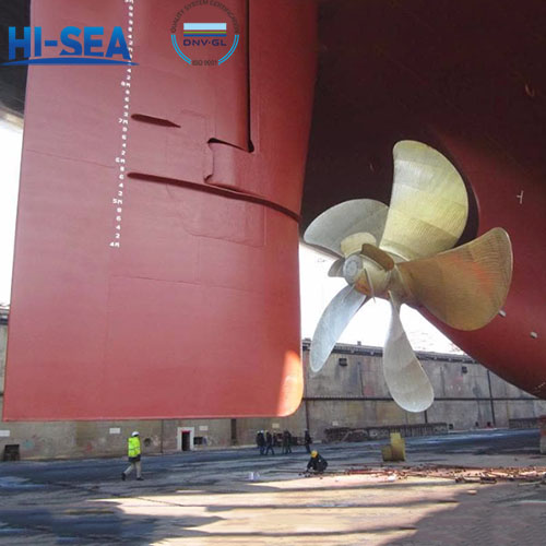
The installation position of propellers requires strict adherence to ship design and manufacturing standards during installation. Generally speaking, the position of ship propeller devices is related to factors such as ship model, ship size, sailing speed, and power output. When determining the installation position of the propeller, it is necessary to set it according to the requirements based on the ship design drawings and actual surveying data. At the same time, the clearance between the propeller and the hull or bottom of the ship should also be considered to ensure assembly quality and safety.
Overview
1. Ship high-speed, energy-saving, bi-directional force propeller installation method
The "Ship High speed Energy saving Dual directional Force Propeller Placement Method" is a different placement scheme proposed based on the existing propeller technology structure; Due to the current propeller placement method, which can only generate unidirectional force and single function, the propeller can only perform less than half of its intended function, wasting more than half of the energy and causing the ship's speed to be too low; The present invention can enable the propellers to generate bi-directional multifunctional force, fully tapping into the potential of the propellers, resulting in a significant increase in speed and energy savings. The propeller is installed in a pipeline that runs through the front and rear of the ship. Its inlet is at the bow of the ship and the outlet is at the stern. When the propeller rotates and works, the water flow in front of the ship is quickly drawn through the inlet to the stern of the ship, creating a recoil force. On the other hand, when the propeller sucks in the water flow in front of the ship, its inlet can also generate a low-pressure traction force.
2. Large ship propeller vertical pre installation device
A large ship propeller vertical pre installation device, comprising a base and a lifting device. The base is composed of a panel, a seat plate, a vertical plate, a support tube, and an adjustment plate. The panel is equipped with bolt holes for fastening the propeller to the base during propeller pre installation. The support tube and the vertical plate are matched at least four times and are respectively arranged between the panel and the seat plate. The upper and lower ends of the support tube are fixedly connected to the panel and the seat plate, and one side of the vertical plate is fixedly connected to the support tube. The upper and lower ends of the vertical plate are fixedly connected to the panel and the seat plate. There are several adjustment plates arranged on the seat plate, and each adjustment plate is equipped with adjustment screws for adjusting the level of the adjustment base. The lifting device consists of a flange, lifting ears, and reinforcement plates. The lifting ears are fixedly connected to the flange, and reinforcement plates are arranged on both sides of the lifting ears. The reinforcement plates are fixedly connected to the flange and lifting ears. The bolt holes on the flange correspond to the bolt holes on the pre installed stern shaft flange. Its advantages are simple device structure, strong on-site operability, and safe pre installation.
3. Installation device between large propeller shaft and stern tube
A installation device for a large propeller shaft and stern tube with small clearance fit on a large ship, consisting of a longitudinal track bracket (11), a longitudinal track (10), and a small car placed on the longitudinal track (10). The car consists of longitudinal walking wheels (8), fixed brackets (7), lateral limit bars (9), upper and lower movable brackets (5), upper and lower adjustment screws (6), sliding plates (3), left and right adjustment screws (4), and pads (2). The longitudinal walking wheel (8) is installed on a fixed bracket (7) and placed on two longitudinal tracks (10). The lateral limit strip (9) is arranged on the top of the two longitudinal tracks (10). The upper and lower movable brackets (5) are placed above the fixed bracket (7) and connected to the fixed bracket (7) with two upper and lower adjustment screws (6) respectively. The sliding plate (3) has two pieces, one on each side, placed on the left and right movable brackets (5) respectively, and connected to the left and right movable brackets (5) with two left and right adjustment screws (4) respectively. The pad (2) has two pieces, placed on the inclined surface of the top of the left and right sliding plates (3) respectively. This utility model is simple, reliable, and practical.
4. Adjustable propeller with integral guide frame
An adjustable propeller using an integral guide frame, comprising a hub, an oil cylinder, a piston, a guide frame, a blade packing, a slider, and a stern shaft. The guide frame is formed by a hollow shaft passing through the center of a square body to form an integral guide frame, and each corner of the square body is provided with a crank pin; One end of the hollow shaft is connected to the piston, and the other end is connected to the inner hole of the stern shaft; The blade root is equipped with a guide groove, and the crank pin on the integral guide frame is placed in the guide groove of the blade root through a slider.
Its advantages are: due to the use of an integral guide frame structure, it can reduce the number of parts, machining volume, and ship inspection costs, and enhance the reliability of parts; Due to the absence of crank pins on the blade root and the use of guide grooves, the size of the blade root blank has been reduced, resulting in lower costs and reduced rough machining volume; Adopting an integral guide frame makes the installation of the entire adjustable propeller more convenient.
For more marine propeller information, kindly please click here.

