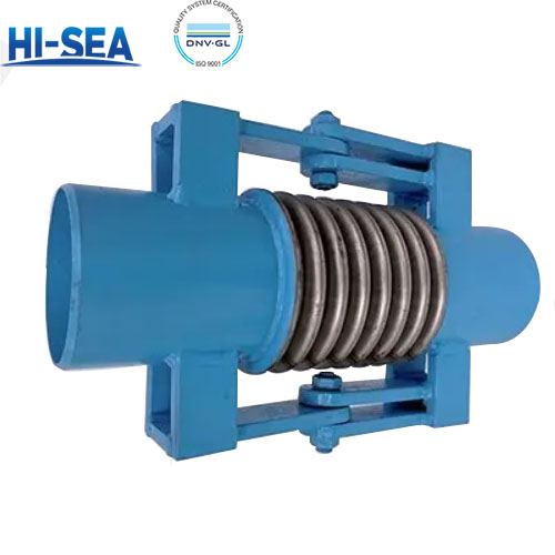
Hinged Pipe Expansion Joint
Hinged Pipe Expansion Joints are a kind of pipe connectors, consisting of a bellows, two sets of hinged plates connected to the end pipe and a pair of pins, etc. Usually used in two or three as a group, used to absorb the transverse displacement in one or more directions in a single plane pipe system. The main purpose is to solve the problem of the pipeline in the process of using. It is mainly used to solve the problem of stress caused by temperature change, vibration and pipe structure during the use of pipeline, so as to reduce the stress of pipeline and prevent pipeline leakage.
Overview
Function
It is mainly used to absorb transverse displacement in one or more directions in a single plane pipe system.
It is capable of absorbing the angular displacement caused by thermal expansion or contraction in the axial direction of pipelines, conveying channels, or containers, etc., by changing the angle.
Structural composition
Bellows: Bellows is the main working body of hinged expansion joint, which is elastic and can absorb the displacement of pipeline.
Hinge plate: The hinge plate is connected to the end pipe and connected by a pin to limit the expansion and contraction of the expansion joint, so that it can only produce angular displacement, thus absorbing lateral displacement.
Pin: The pin is used to connect the hinge plate to the bellows to ensure flexible rotation and displacement absorption of the expansion joint.
Advantages
Strong elongation and contraction capacity: The hinged expansion joint has a certain elongation and contraction capacity, which can effectively reduce the stress caused by temperature changes in the pipeline and protect the integrity and safety of the pipeline.
Strong pressure-bearing capacity: after rigorous testing and selection of materials, hinged expansion joints have strong pressure-bearing capacity, can withstand high pressure and high temperature and other extreme working conditions, to ensure the safe operation of the pipeline system.
Good corrosion resistance: stainless steel, carbon steel, zirconium alloy and other corrosion-resistant materials are usually used, which can effectively resist strong acid, alkali, high concentration of brine and other corrosive media to extend the service life.
Convenient installation: Because of the flange connection, it is very convenient to install and maintain without large-scale construction and dismantling, which greatly shortens the production downtime and maintenance costs.
Technical parameters
The design temperature range is typically -20 to 450 degrees Celsius and the design pressure range is 0.1 to 2.5 MPa.
Nominal diameters range from DN50 to DN3000 mm.
Design temperature:-20℃-+450℃ | ||||||
Nominal Diameter DN | Wavenumber | Length of the grade MPa | ||||
0.25 | 0.6 | 1.0 | 1.6 | 2.5 | ||
Length mm/Angle to compensate for the amount of mm/(angle)/Stiffness N.M angle | ||||||
150 | 4 | 600/±6.1/12 | 600/±5.0/23 | 600/±4.3/36 | 600/±3.4/76 | 600/±3.0/87 |
200 | 600/±8.9/23 | 600/±6.4/50 | 650/±5.1/115 | 650/±43/115 | 700/±3.5/278 | |
250 | 600/±6.8/36 | 600/±4.9/79 | 650/±3.6/200 | 650/±3.3/320 | 700/±3.9/489 | |
300 | 650/±7.2/36 | 650/+4.9/109 | 650/±4.0/278 | 750/±3.5/488 | 750/±3.2/594 | |
350 | 650/±7.0/49 | 650/±3.9/109 | 700/±3.3/314 | 750/±2.8/765 | 800/±2.7/832 | |
400 | 650/±5.5/78 | 66/±4.2/123 | 700/±3.5/502 | 750/±2.6/987 | 850/±3.0/1186 | |
450 | 750/±5.0/98 | 750/±3.4/293 | 750/±2.9/754 | 850/±2.9/1675 | 100/±2.2/1312 | |
500 | 750/±5.1/121 | 750/±3.3/469 | 750/±2.2/987 | 850/±1.9/1532 | 100/±2.3/2145 | |
600 | 850/±6.1/187 | 850/±4.4/399 | 900/±3.2/1869 | 1000/±2.9/1150 | 1100/±2.0/2254 | |
700 | 850/±5.9/185 | 850/±4.2/577 | 950/±3.8/768 | 1100/±3.0/1507 | ||
800 | 900/±5.5/455 | 900/±3.4/764 | 1000/±3.9/1665 | 1100/±2.6/2987 | ||
900 | 900/±4.9/364 | 300/±3.3/1054 | 1100/±3.8/1562 | 1200/±2.2/3398 | ||
1000 | 1000/±5.1/948 | 1000/±3.2/2020 | 1100/+2.9/5648 | 1200/±2.5/5064 | ||
1100 | 1000/±4.2/765 | 1000/±3.1/2525 | 1100/±2.8/7589 | 1300/±26/7365 | ||
1200 | 1000/±4.1/769 | 1000/±2.8/3386 | 1200/±3.1/9870 | 1400/±2.9/7598 | ||
1400 | 110/±3.1/1366 | 1100/±2.2/5648 | 1200/±2.2/16630 | |||
1500 | 110/±3.9/1864 | 1100/±2.1/6489 | 1300/±2.5/13353 | |||