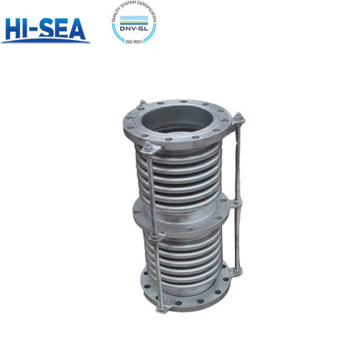
Duplex Rod Axial Expansion Joint
Duplex rod axial expansion joint is a kind of compensator with large compensation capacity and simple structure, whose main structure consists of two (or more than two) bellows and short intermediate receiver and guide rod, which has bending resistance and guiding performance, and is capable of absorbing the axial displacement of the pipeline and ensuring that the bellows are not destabilized when working. They are usually used in pipelines with low fatigue frequency that require large compensation.
Overview
Application
Duplex rod axial expansion joint is generally used in low fatigue times of pipelines which need large compensation quantity, such as places with complex geological conditions, large settlement and frequent hot and cold changes in pipeline operation. Its simple structure and large compensation quantity are especially suitable for such occasions requiring large displacement compensation.
Installation and maintenance
(1) Check the nameplate: before installation, it is necessary to check whether the nameplate of the compensator is in accordance with the provisions of the construction drawings, and to check the appearance of the compensator.
(2) Adjust the limit nuts: after installation, the limit nuts at both ends should be adjusted to the rated compensation value or a little larger, but not removed.
(3) Installation direction: when equipped with liner cylinder, its direction should be the same as the medium flow direction (there is a flow direction sign on the expansion joint).
(5) Fixing nut: after installation on site, the nuts on both sides of the directional lugs must be backed up to the limiting nut.
Nominal Diameter DN mm | Bellows | Axial compensation X0 mm | Axial stiffness Kx0 N/mm | Radial shape Maximum size B mm | Product Length L mm | Product Type | ||
Wavenumber n | Effective area A cm2 | Connection mode | ||||||
Take over J | Flange F | |||||||
Design pressure Pd=0.6MPa (6kgf/cm2) Fatigue life [N]=200 Design temperature t=20℃ | ||||||||
80 | 20 | 108 | 127 | 69 | 290 | 900 | 910 | FZ |
100 | 145 | 126 | 80 | 310 | ||||
125 | 205 | 123 | 95 | 340 | ||||
150 | 275 | 120 | 112 | 380 | ||||
200 | 16 | 547 | 244 | 106 | 460 | 1150 | 1170 | FZS |
250 | 794 | 241 | 124 | 530 | ||||
300 | 1104 | 308 | 110 | 580 | 1300 | 1320 | ||
350 | 1432 | 306 | 123 | 660 | ||||
400 | 1787 | 303 | 136 | 720 | ||||
450 | 2198 | 298 | 150 | 780 | ||||
500 | 2642 | 294 | 163 | 850 | ||||
600 | 3759 | 431 | 209 | 1000 | 1800 | 1824 | ||
Design pressure Pd=1.0MPa (10kgf/cm2) Fatigue life [N]=200 Design temperature t=20℃ | ||||||||
80 | 20 | 108 | 105 | 112 | 290 | 900 | 910 | FZ |
100 | 146 | 103 | 132 | 310 | ||||
125 | 205 | 99 | 160 | 340 | ||||
150 | 276 | 95 | 189 | 380 | ||||
200 | 16 | 551 | 201 | 174 | 460 | 1150 | 1170 | FZS |
250 | 798 | 195 | 211 | 530 | ||||
300 | 1109 | 252 | 180 | 580 | 1300 | 1320 | ||
350 | 1437 | 248 | 204 | 560 | ||||
400 | 1793 | 243 | 227 | 720 | ||||
450 | 2205 | 238 | 252 | 780 | ||||
500 | 2649 | 233 | 276 | 850 | ||||
600 | 3772 | 343 | 368 | 1000 | 1800 | 1824 | ||
Design pressure Pd=1.6MPa (16kgf/cm2) Fatigue life [N]=200 Design temperature t=20℃ | ||||||||
80 | 20 | 108 | 124 | 155 | 290 | 900 | 910 | FZK |
100 | 145 | 123 | 181 | 310 | ||||
125 | 204 | 120 | 215 | 340 | ||||
150 | 275 | 117 | 253 | 380 | ||||
200 | 16 | 551 | 211 | 372 | 460 | 1150 | 1160 | FZS |
250 | 798 | 205 | 450 | 530 | ||||
300 | 1109 | 257 | 407 | 580 | 1300 | 1320 | ||
350 | 1437 | 253 | 461 | 660 | ||||
400 | 1793 | 248 | 514 | 720 | ||||
450 | 2205 | 243 | 570 | 780 | ||||
500 | 2649 | 239 | 625 | 850 | ||||
600 | 3772 | 336 | 679 | 1000 | 1800 | 1824 | ||
The recommended values of θ (θ max'') | |||||||||||
Nominal Diameter | ≤200 | 250 | 300 | 350 | 400 | 450 | 500 | 600 | 700 | ≥800 | |
θ max | n group | 50 | 45 | 42 | 40 | 35 | 32 | 30 | 28 | 26 | 23 |
Ω group | ≤60 | ||||||||||
The main technical parameters table | ||||||
Sequence Number | Nominal diameter | Compensation amount Δ(mm) | Take over the outside diameter | Flange OD | Length L (mm) | Torque M(KN.m) |
D1(mm) | D2(mm) | |||||
1 | 50 | 0~1000 | 57 | 189 | 380 | 0.584 |
2 | 65 | 0~1000 | 76 | 208 | 380 | 0.72 |
3 | 80 | 0~1000 | 89 | 233 | 380 | 1.11 |
4 | 100 | 0~1000 | 108 | 252 | 380 | 1.29 |
5 | 125 | 0~1000 | 133 | 268 | 380 | 1.83 |
6 | 150 | 0~1200 | 159 | 303 | 380 | 2.35 |
7 | 200 | 0~1200 | 219 | 373 | 400 | 3.93 |
8 | 250 | 0~1500 | 273 | 425 | 420 | 8.11 |
9 | 300 | 0~1800 | 325 | 477 | 440 | 14.48 |
10 | 350 | 0~1800 | 377 | 526 | 460 | 18.5 |
11 | 400 | 0~1800 | 426 | 580 | 460 | 25.84 |
12 | 450 | 0~2000 | 480 | 630 | 460 | 36.21 |
13 | 500 | 0~2000 | 530 | 690 | 480 | 45.12 |
14 | 600 | 0~2000 | 630 | 790 | 480 | 63.23 |
15 | 700 | 0~2000 | 720 | 930 | 500 | 72.7 |
16 | 800 | 0~2000 | 820 | 1028 | 500 | 93.2 |
17 | 900 | 0~2000 | 920 | 1130 | 520 | 110.5 |
18 | 1000 | 0~2000 | 1020 | 1236 | 520 | 125 |
19 | 1100 | 0~2000 | 1120 | 1342 | 530 | 145.6 |
20 | 1200 | 0~2000 | 1220 | 1438 | 530 | 163.7 |
21 | 1300 | 0~2000 | 1320 | 1536 | 540 | 186.1 |
22 | 1400 | 0~2000 | 1420 | 1642 | 550 | 202.5 |
23 | 1500 | 0-2000 | 1520 | 1750 | 560 | 228.7 |
24 | 1800 | 0~2000 | 1910 | 2050 | 600 | 305.4 |
25 | 2000 | 0~2000 | 2110 | 2110 | 610 | 386.2 |

