
Design and Structure of Marine Air Compressors
The design and structure of marine air compressors need to meet the special requirements of the marine environment to ensure their long-term reliable operation under harsh conditions.
The air compressor should have a pressure gauge indication, which can have waterproof or night light display function as needed.
Lubricating oil supply holes, oil level gauges, oil drain plugs, explosion-proof valves, and ventilation devices should be installed above the crankcase.
In the cooling system of a water-cooled air compressor, components in contact with cooling water should be protected against rust and corrosion, and equipped with cooling water discharge channels to facilitate drainage inside the cylinder.
Overview
Design and Structure
1. The air compressor should have a pressure gauge indicating, which can have waterproof or night light display function as needed.
2. Lubricating oil supply holes, oil level gauges, oil drain plugs, explosion-proof valves, and ventilation devices should be installed on the crankcase.
In the cooling system of a water-cooled air compressor, components in contact with cooling water should be protected against rust and corrosion, and equipped with cooling water discharge channels to facilitate drainage inside the cylinder.
4. The water-cooled air compressor should be equipped with a cooler, and the multi-stage compression water-cooled air compressor should be equipped with an intermediate cooler and an aftercooler. A cooling water safety valve or safety film should be installed on the cooler, and a drain plug or valve should be installed. A small fusible plug or alarm device should be installed at the outlet of the aftercooler of the air compressor, and an alarm should be triggered when the air temperature exceeds 121 ℃.
5. The air compressor should be equipped with a unloading mechanism, and in situations where automatic control is used, it should have a mechanism that can be manually operated.
6. The air compressor should be equipped with a liquid gas separator (air-cooled air compressors with a nominal volume flow rate not exceeding 24 m3/h may not be installed).
7. The connection of the air pipe, water pipe, and oil pipe of the air compressor should be sealed, easy to disassemble, and able to prevent vibration.
When the exhaust port and cooling water inlet and outlet external pipelines of the air compressor are connected using a flange structure, the external flange of the air compressor should comply with the provisions of GB/T 2506 and GB/T 10746.
9. The suction port of the air compressor should be equipped with an air filter.
10. The automatic control device of the air compressor can be divided into two modes: semi-automatic and fully automated:
a) The semi-automatic form includes automatic startup, automatic shutdown, automatic unloading, and automatic discharge
b) The fully automated form includes automatic startup, automatic shutdown, automatic unloading, automatic discharge, and additional necessary automatic protection devices and alarm devices.
11. Exposed moving parts should be equipped with protective covers mainly made of metal wire mesh or steel plates.
12. The actual mass of the piston, connecting rod, and balance iron should not deviate from the mass shown on the drawing by more than the following provisions:
a) Pistons: ± 3%;
b) Connecting rod: ± 3%; c) Balance iron: ± 4%.
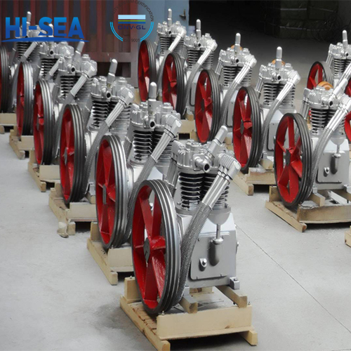
13. The flywheel (pulley) should undergo static balance correction.
14. To make it easy to reset the air compressor head and prime mover after disassembly, positioning pins should be used between the air compressor head and the common base, as well as between the prime mover and the common base.
Environmental adaptability:
The air compressor should be able to be used under the following conditions and meet the following requirements:
a) Roll: ±22.5°
b) Longitudinal sway: ±7.5°
c) Lateral inclination: ±15°
d) Vertical inclination: ±5°
e) Environmental temperature: 5℃~45℃
f) The maximum inlet water temperature for cooling seawater is 32℃
g) The maximum inlet temperature of fresh water for closed loop cooling is 40℃
h) The air entering the air compressor contains trace amounts of oil mist and salt mist, with a maximum relative humidity of 95%.
For more marine air compressor information, please click here.