
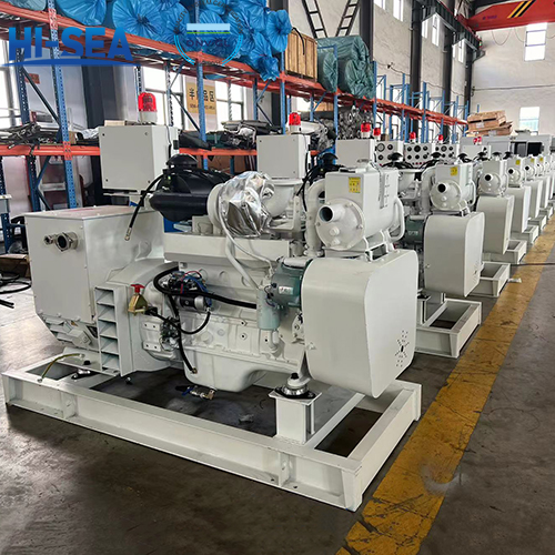
Definitions of marine generating sets
It is composed of a diesel engine, generator, and a common chassis, including a diesel engine speed control device and a simple engine side instrument panel. If the instrument panel is replaced by an engine side control box and has safety, protection, and other functions, the engine side control box should comply with the requirements of CCS "Classification Specification for Steel Seagoing Ships" and be inspected separately, unless it is clearly stated in the diesel engine certificate.
Overview
1. Diesel generating set is a generating set consisting of a diesel engine, a generator and their common bedplate, including an engine governor and a simple local instrument panel. If the panel is replaced by a local control box with safety and protection functions, the control box is to
comply with the requirements of CCS Rules for Classification of Sea-going Steel Ships and be separately inspected, unless the box is indicated in the diesel engine certificate.
2. Emergency diesel generating set is a generating set consisting of an emergency diesel engine, an emergency generator and their common bedplate, including an engine governor, a simple local instrument panel, a double power starting device, coolers and cooling fans. If the above-mentioned accessories are not covered by the emergency diesel engine certificate, the accessories are to be certified by CCS. If the panel is replaced by a local control box with safety and protection functions, the control box is to comply with the requirements of CCS Rules for Classification of Sea-going Steel Ships and be separately inspected, unless the box is indicated in the diesel engine certificate.
3. Degree of protection means the protection which enables the generating set to operate without any injury or harmful impacts under the environmental conditions as defined in IEC 60529.
4. Emergency load means the maximum emergency load to be applied in an emergency on ships.
5. Rated power of a diesel engine is the continuous power of the diesel engine under certain environmental conditions, to be corrected for inland-waters ships and sea-going ships according to the actual environmental conditions.
6. Steady-state governing characteristic curve of generating sets
Operating at the rated load and speed, the load of the generating set with a fixed governing mechanism changes reciprocally in single direction within the range from no load to full load and the curve is formed by connecting arithmetrical means of speed power characteristic loops.
7. Steady-state speed governing rate of generating sets
Set at rated load and rated speed, with load changing from no-load to full load or in a reverse way evenly or abruptly, the rate of difference between the stable no-load speed ni and the rated speed nN to the rated speed nN is shown in percentage

where: δst– steady-state speed governing rate, in %;
ni – stable no-load speed, in r/min;
nN– rated speed, in r/ min.
8. Transient speed governing rate and stabilization time for generating sets
(1) Transient speed governing rate of generating sets means the rate of the difference between the minimum transient speed (nmin) or the maximum transient speed (nmax)and the speed (ni) prior to load change or the rated speed (nN) to the rated speed (nN), shown in percentage, where the steady-state speed governing rate is stabilized and a specified symmetrical load is suddenly taken off and then suddenly applied at the rated load and speed.
The transient speed governing rate δd at the maximum transient speed is to be calculated according to Formula (2).

The transient speed governing rate δd at the minimum transient speed is to be calculated according to Formula (3).

(2) Stabilization time means the time required from the commencement of speed variation until the speed returns to a level where its deviation from the steady-state speed at the related load is within the range of speed fluctuation rate. See Figure 8.(2)
 Process of Transient Speed Change.png "Figure 8.(2) Process of Transient Speed Change.png")
9. Insensitivity of governing system for generating sets
The insensitivity means the ratio of the maximum vertical distance △ n between speed power characteristic loops to the rated speed nN, shown in percentage, where the steady-state speed governing rate is stabilized and the load of the generating set changes reciprocally in single direction within the range from no load to full load. See Figure 9.


10. Non-linearity of steady-state speed governing characteristics
The ratio of the maximum speed deviation as shown between the lines connecting the steady-state governing characteristic curve with the corresponding no load and rated load points to the rated speed, that is, the relative speed difference as shown between the line connecting no load and full load points of the governing characteristic curve and the straight line which is tangential to the steady-state speed governing characteristic curve and parallel to the connecting line. See Figure 10.
11. Speed fluctuation rate
Operating at any load within the range of no load to full load, the rate of the difference between the maximum speed n1 or minimum speed n2 measured at certain intervals and their average nm to the average speed nm is shown in percentage.

12. Steady-state voltage regulation rate
This is the ratio of the difference between the maximum or minimum voltage u within the loop reciprocally changing in single direction from no load to full load and the rated voltage uN to the rated voltage uN, shown in percentage, where the steady-state speed governing rate is stabilized and the excitation voltage regulation system remains unchanged to maintain the load power factor at its rated value.

13. Transient voltage variation and stabilization time
The rate of the difference between the minimum or maximum transient voltage u’ and the voltage u0 prior to load change to the rated voltage uN is shown in percentage where the steady-state speed governing rate is stabilized and a specified symmetrical load, of which the power factor is 0.4 (lag) or less, is suddenly applied and then suddenly taken off at the voltage regulation rate.

where: △ u – transient voltage variation, in %;
U’– minimum or maximum transient voltage, in V;
u0– voltage prior to load change, in V.
Setting time is the time period starts from the voltage changes till the deviation between voltage and required voltage falls within 1-3% of rated voltage.
14. Voltage fluctuation rate
Operating at the set governing characteristics at any load from no load to full load, the rate of the difference between the maximum voltage u1 or the minimum peak voltage u2 measured at certain intervals and their average value um to the average voltage um is shown in percentage.

15. Difference of load sharing
The difference between the actual load on the ith one of generating sets operating in parallel and the total average load.

16. COP: Continuous power
17. PRP: Prime power
18. LTP: Limited-time running power.
For more marine diesel generator set information, kindly please click here.