
Arrangement of shaft system
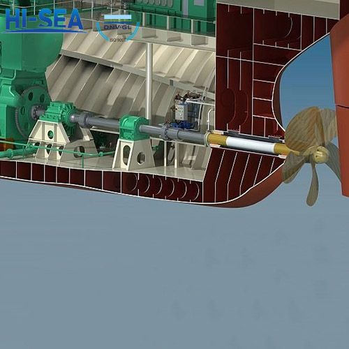
The arrangement of ship shaft system refers to the structure and arrangement of the transmission system and propulsion system on the ship. It usually involves the position and connection method of components such as the main engine, shaft line, propeller, and thruster.
Overview
As shown in Figures 1-16, the arrangement of the shaft system is based on the requirements of the "shaft line".

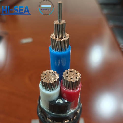
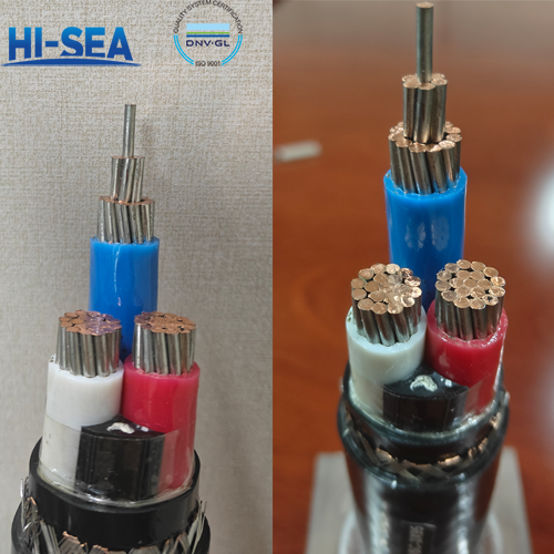
The shaft system between the main engine and the propeller is connected by several shafts on the same straight line, which we call the "axis".
The number of axes is often determined based on the type of vessel, navigation performance, engine type, and reliability. Generally, large and medium-sized civilian ships have dedicated single-shaft lines. Most warships, passenger ships, and special vessels adopt a double-shaft line or triple-shaft line arrangement, as shown in Figures 1-17 and 1-18.
The shaft line of a single shaft is usually arranged on the centerline of a ship. The shaft line of the double shaft is symmetrically arranged on both sides of the ship's centerline. The three-shaft line has one shaft arranged on the centerline surface, while the other two are symmetrically arranged on both sides of the centerline surface. The layout of the four-shaft line is shown in Figure 1-19 (b).
The height of the shaft line usually needs to match the arrangement height and position of the main engine and propellers.
The ideal arrangement for the shaft line of the shaft system should be parallel to the baseline of the ship. The axis layout of the 10000-ton cargo ships built in our country is mostly parallel to the hull baseline.
However, for special vessels such as technology research vessels and small and medium-sized warships, their main engine positions are relatively high. Especially when the draft is shallow, to ensure that the propeller is submerged in water at a certain depth and improve the efficiency of propeller propulsion characteristics, the axis is tilted to a certain angle towards the stern of the ship, as shown in Figure 1-19 (a).
Such as the longitudinal inclination angle of the shaft line angle of trim α 0 °~ 5 °, which is used on the famous "Yuanwang" space survey ship. And some small high-speed warships, workboats, etc. have a longitudinal inclination angle between their axis and the baseline, even reaching 10 °~16 °

 marine shaft system diagram.jpg "Figure 1-18 (Double shaft system) marine shaft system diagram.jpg")
Some double-shaft ships allow a small deviation angle between the horizontal projection line of the axis and the centerline of the ship to maintain a certain distance between the propeller blade tips and the hull( β), Generally ranging from 0 ° to 30 °, as shown in Figure 1-19 (b).
What is "hull baseline"? The baseline is a straight line parallel to the design waterline drawn through the intersection point between the hull keel line and the midship transverse section line. It is the theoretical line of the ship's hull and an important basis for students and employees to refer to the ship's hull structure diagram for construction.


For more marine shaft system information, kindly please click here.
For more marine shaft system components, kindly please click here.